Optical multi-level transmission system
a transmission system and optical multi-level technology, applied in the field of optical information transmission technology, can solve the problems of significant degraded reception sensitivity, and achieve the effect of improving the efficiency of optical multi-level transmission
- Summary
- Abstract
- Description
- Claims
- Application Information
AI Technical Summary
Benefits of technology
Problems solved by technology
Method used
Image
Examples
first embodiment
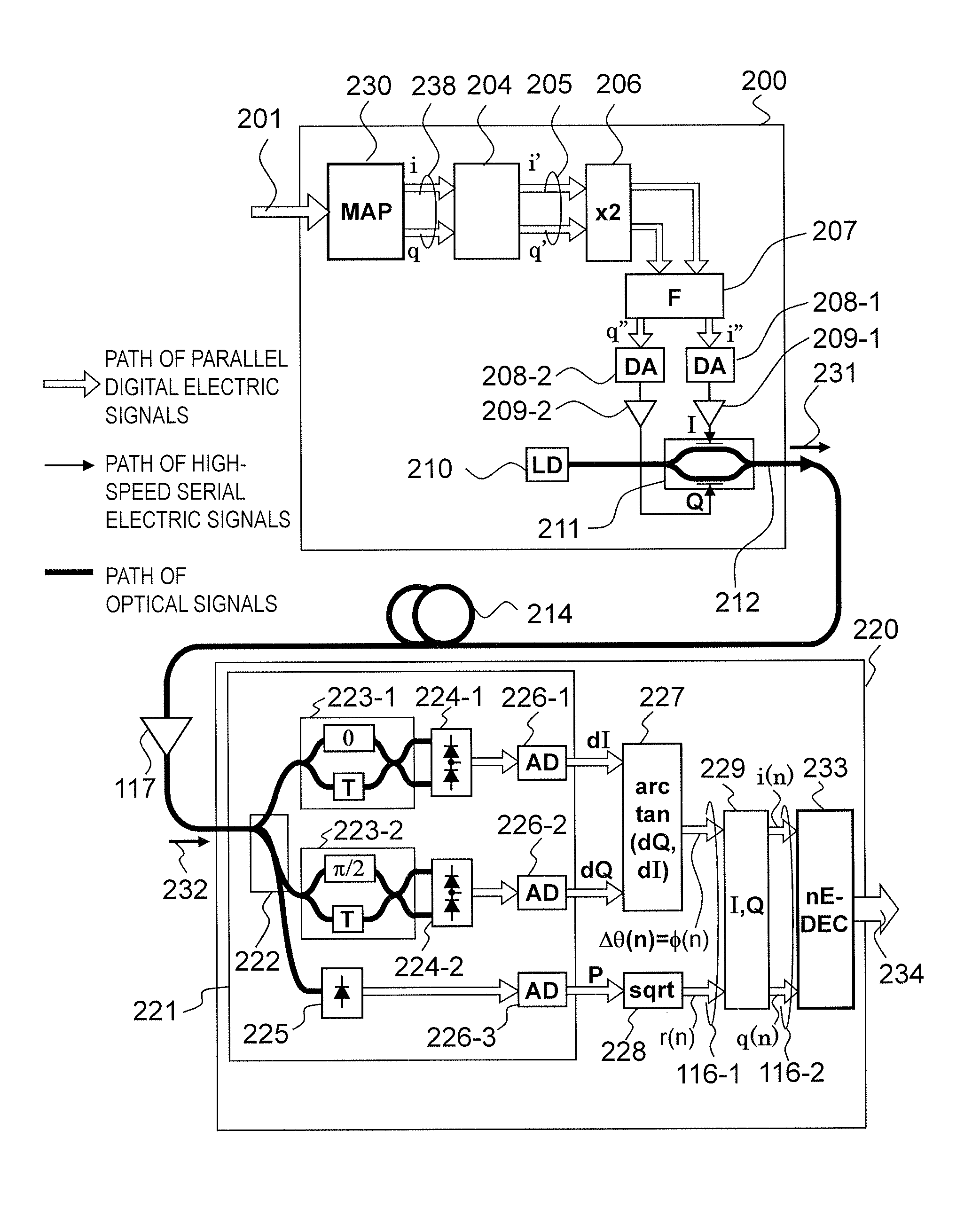
[0102]FIG. 5 is a block diagram illustrating a phase pre-integration incoherent optical multilevel transmission system according to this invention.
[0103]Hereinafter, a path of optical signals is indicated by a bold line, a path of electric signals is indicated by a thin line, and a path of parallel digital electric signals using a plurality of signal wires is indicated by white open arrows. This configuration is an incoherent optical multilevel transmission system using a phase pre-integration optical field transmitter 200 and an incoherent optical field receiver 220.
[0104]A first difference between the conventional technology illustrated in FIG. 4 and this embodiment resides in a symbol decision circuit inside the incoherent optical field receiver 220, and in this embodiment, a symbol decision circuit 233 which uses an amplitude-weighted non-Euclidean distance is used.
[0105]A second difference between the conventional technology illustrated in FIG. 4 and this embodiment resides in ...
second embodiment
[0133]FIG. 8 is an explanatory diagram illustrating a signal constellation of 8QAM modulation according to this invention, and a decision area for a received symbol based on the non-Euclidean distance.
[0134]This invention takes an example in which an 8QAM signal is used as the modulation signal and in which the non-Euclidean distance d(X,Y) is used to define the decision area. In this example, in dE(x,y)=|x−y|^2+a(|x|−|y|) ^2, the amplitude weight a is set to 2. As a result, the decision areas for all the symbols are enlarged to near 90 degrees in the angular direction on the dotted circumference on which each symbol is located, and hence the resistance to the noise in the angular direction is significantly improved compared to the decision areas described above with reference to FIG. 7B. Further, the boundary lines generally coincide with sparse regions of the eight distributions of black dots, which also demonstrates that near-ideal decision can be made.
third embodiment
[0135]FIGS. 9A to 9C are explanatory diagrams each illustrating a signal constellation and decision areas for the received symbol based on the non-Euclidean distance of 16QAM modulation according to this invention.
[0136]FIGS. 9A to 9C are explanatory diagrams illustrating the signal constellation and a decision area for a received symbol based on a non-Euclidean distance when the weight a is set to 1 to 3 of the 16QAM modulation according to the third embodiment of this invention.
[0137]This invention takes an example in which the 16QAM signal is used as the modulation signal and in which the non-Euclidean distance d(X,Y) is used to define the decision area. The definition of d(X,Y) in this example is the same as the second embodiment, but the amplitude weight a is changed to examine the change in the decision area. FIGS. 9A to 9C illustrate cases where a=1, a=2, and a=3, respectively, and it can be seen from the figures that as the amplitude weight a is set larger, the width of the ...
PUM
 Abstract
Description
Claims
Application Information
 - R&D
- Intellectual Property
- Life Sciences
- Materials
- Tech Scout
- Unparalleled Data Quality
- Higher Quality Content
- 60% Fewer Hallucinations
Browse by: Latest US Patents, China's latest patents, Technical Efficacy Thesaurus, Application Domain, Technology Topic, Popular Technical Reports.
© 2025 PatSnap. All rights reserved.Legal|Privacy policy|Modern Slavery Act Transparency Statement|Sitemap|About US| Contact US: help@patsnap.com


