
Lens positioning unit of optical system

a technology of optical system and positioning unit, applied in the direction of printers, cameras, instruments, etc., can solve the problem of difficulty in realizing pure vertical motion

Active Publication Date: 2014-02-18
SAMSUNG ELECTRONICS CO LTD
View PDF13 Cites 5 Cited by
  • Summary
  • Abstract
  • Description
  • Claims
  • Application Information

AI Technical Summary

Benefits of technology

The solution enables precise micron-level axial adjustment of lenses without parasitic motion in non-axial directions, enhancing the accuracy and reliability of optical systems and facilitating maintenance in applications like LCD and semiconductor exposure apparatuses.

Problems solved by technology

However, this method causes rotation of an optical axis of the lens and has difficulty realizing pure vertical motion due to backlash and irregularity of screws.

Method used


Image

  • Lens positioning unit of optical system
  • Lens positioning unit of optical system
  • Lens positioning unit of optical system

Examples


Embodiment Construction

[0030]Example embodiments will now be described more fully with reference to the accompanying drawings, in which some example embodiments are shown. Example embodiments, may, however, be embodied in many different forms and should not be construed as being limited to the embodiments set forth herein; rather, these example embodiments are provided so that this disclosure will be thorough and complete, and will fully convey concepts of example embodiments to those of ordinary skill in the art. In the drawings, the thicknesses of layers and regions are exaggerated for clarity. Like reference numerals in the drawings refer to like elements throughout, and thus their description will be omitted.

[0031]It will be understood that when an element is referred to as being “connected” or “coupled” to another element, it can be directly connected or coupled to the other element or intervening elements may be present. In contrast, when an element is referred to as being “directly connected” or “d...


PUM


Abstract

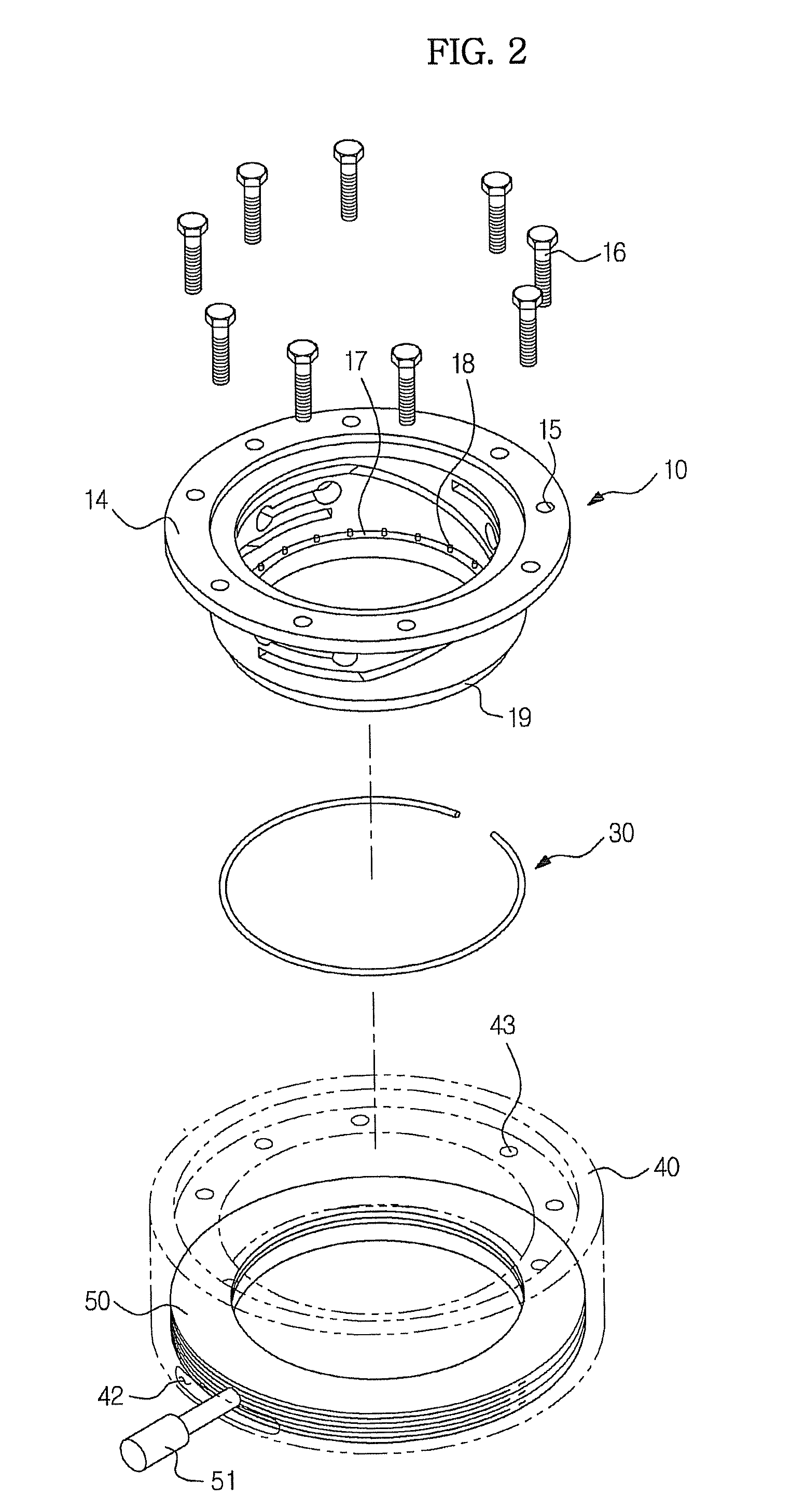
According to example embodiments, a lens positioning unit includes a fixed structure, a monolithic flexure hinge structure, any one of upper and lower portions of which is provided with a lens mount on which a lens is mounted and the other portion of which is secured to the fixed structure, and an input unit rotatably coupled to the fixed structure, the input unit serving to convert rotational motion into vertical translational motion so as to transmit the vertical translational motion to the upper or lower portion of the monolithic flexure hinge structure provided with the lens mount.

Description

CROSS-REFERENCE TO RELATED APPLICATION[0001]This application claims priority under 35 U.S.C. §119 to the benefit of Korean Patent Application No. 2010-0130220, filed on Dec. 17, 2010 in the Korean Intellectual Property Office, the entire disclosure of which is incorporated herein by reference.BACKGROUND[0002]1. Field[0003]Example embodiments relate to a lens positioning unit of an optical system usable with an exposure apparatus, which performs lens position adjustment with one degree of freedom of micron-level precision within a minimum space.[0004]2. Description of the Related Art[0005]In order to assemble a barrel type optical system usable with an exposure apparatus, a large-diameter lens may be mounted in a unit cell barrel and precise stacking of cells may be performed.[0006]The optical system assembled in the above-described manner may require adjustment of an infinitesimal axial distance between lenses for correction of magnification and aberration. In this case, reducing an...

Claims


Application Information

Patent Timeline
Patent Type & Authority Patents(United States)
IPC IPC(8): G02B7/02
CPCG02B7/026G02B7/023G02B7/105
Inventor PARK, SANG HYUNJANG, IN BAE
Owner SAMSUNG ELECTRONICS CO LTD
Learn More