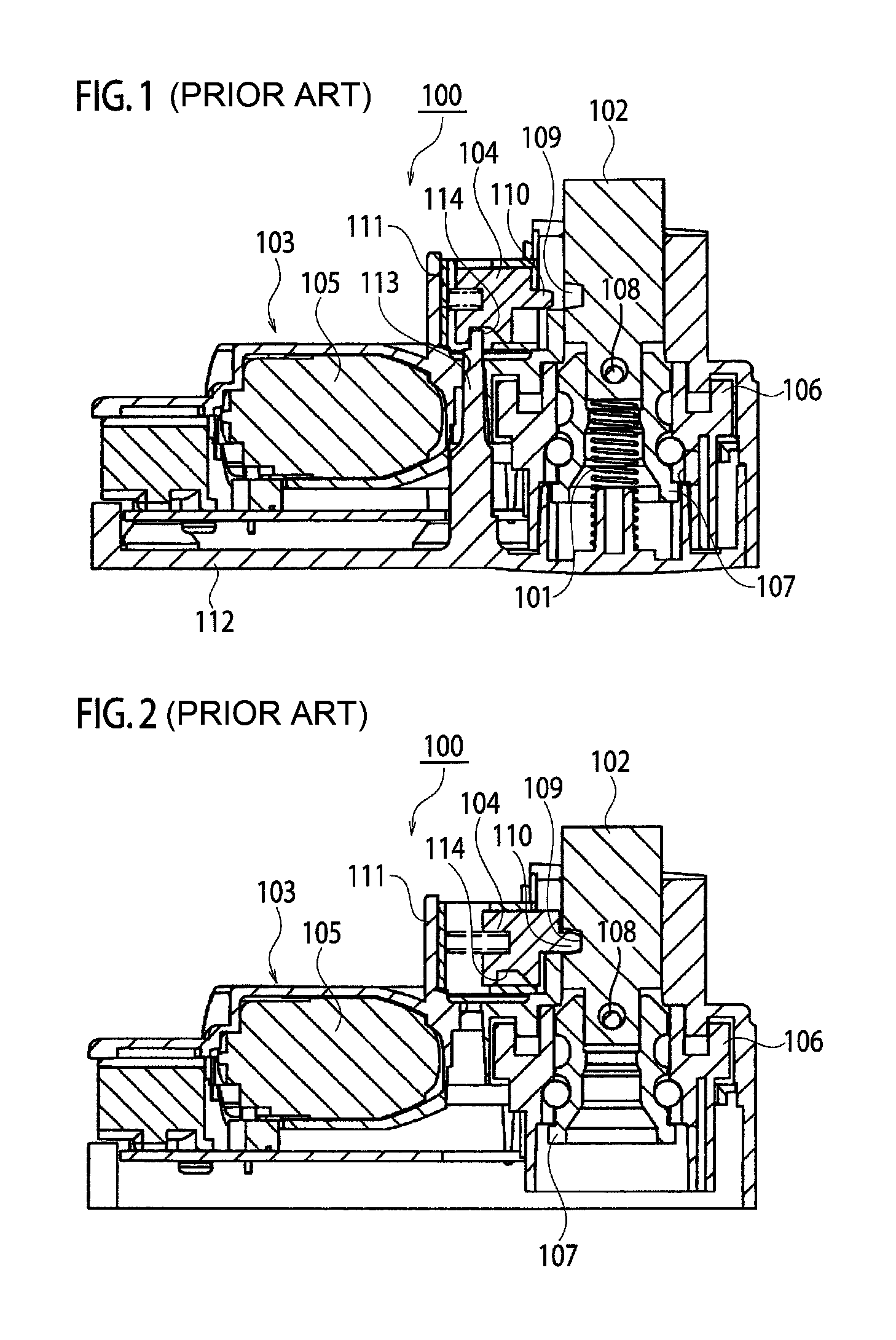
Steering locking device
a locking device and locking mechanism technology, applied in the direction of mechanical control devices, anti-theft devices, instruments, etc., can solve the problems of cumbersome work, difficult arrangement of components in a limited space, theft prevention problems,
- Summary
- Abstract
- Description
- Claims
- Application Information
AI Technical Summary
Benefits of technology
Problems solved by technology
Method used
Image
Examples
first embodiment
[0038]As shown in FIGS. 3 to 12, a steering locking device 1 of First Embodiment includes a cover 2 and a housing 3 which are attached to each other and is attached to a steering column device A accommodating an unillustrated steering shaft of an automobile.
[0039]The housing 3 includes a component accommodating chamber 3a, a lock accommodating hole 3b, and an auxiliary lock accommodating hole 3c which are formed inside the housing 3, and has a pair of leg portions 3d, 3d. The component accommodating chamber 3a is opened toward one side of the steering locking device 1 (a lower side in FIGS. 5, 6, and the like). The lock accommodating hole 3b penetrates the housing 3 from a bottom portion of the component accommodating chamber 3a to the steering column device A side and extends in a vertical direction with respect to an axial direction of the steering shaft. The auxiliary lock accommodating hole 3c extends in a direction orthogonal to the lock accommodating hole 3b. The pair of legs ...
second embodiment
[0066]FIG. 14 shows Second Embodiment of the present invention and is a cross-sectional view showing a steering lock device.
[0067]In a steering locking device 1A in Second Embodiment, the coupling portion 73 of the hanger 7 has a swelling-out portion 73a formed by swelling out of the hanger 7 toward both sides thereof, the arm portions 81, 82 of the lock main body 8 have bent ends 81b, 82b protruding in directions of approaching to each other, and the lock main body 8 is movably coupled to the hanger 7. The bent ends 81b, 82b can lock the swelling-out portion 73a of the hanger 7. The locking member 6 has the wide face B parallel to the axial direction of the steering shaft and the thick face C (the side face of the arm portion 74) perpendicular to the wide face B. The thick face C is provided with an engagement pin 79 as a protrusion engaged with the sliding plate 91. As compared with the steering locking device 1 in First Embodiment, the configuration is the same as that in First E...
third embodiment
[0070]FIG. 15 shows Third Embodiment of the present invention and is a cross-sectional view showing a steering locking device.
[0071]In a steering locking device 1B in Third Embodiment, a protrusion 74b engaged with the sliding plate 91 is provided on a side face of the arm portion 74 of the hanger 7. As compared with the steering locking device 1A in Second Embodiment, the configuration is the same as that in Second Embodiment except the protrusion 74b. Parts in the same configuration as that in Second Embodiment are denoted by the same reference numerals in the drawings, and descriptions thereof will be omitted.
[0072]In the aforementioned configuration, when the cover 2 is removed from the housing 3 in the locked state, the holding portion 21 of the cover 2 is disengaged from the sliding plate 91, and the sliding plate 91 is urged in the direction to the hanger 7. Thus, the sliding plate 91 becomes engaged with the protrusion 74b of the hanger 7. This prevents the movement of the h...
PUM
 Abstract
Description
Claims
Application Information
 - R&D
- Intellectual Property
- Life Sciences
- Materials
- Tech Scout
- Unparalleled Data Quality
- Higher Quality Content
- 60% Fewer Hallucinations
Browse by: Latest US Patents, China's latest patents, Technical Efficacy Thesaurus, Application Domain, Technology Topic, Popular Technical Reports.
© 2025 PatSnap. All rights reserved.Legal|Privacy policy|Modern Slavery Act Transparency Statement|Sitemap|About US| Contact US: help@patsnap.com


