
Key blank identification system with groove scanning

a technology of key blank and identification system, which is applied in the field of identification systems of objects, can solve the problems of increasing the difficulty level of all operators of such key replication system, and affecting the accuracy of key reproduction

Active Publication Date: 2014-02-04
HY KO PRODS
View PDF13 Cites 23 Cited by
  • Summary
  • Abstract
  • Description
  • Claims
  • Application Information

AI Technical Summary

Benefits of technology

The key identification system is designed to capture images of a master key and analyze them to identify the key's unique groove characteristics. This system can account for the position and orientation of the master key to accurately determine the groove's characteristics. The technical effect of this invention is to provide a reliable and accurate means of identifying different keys.

Problems solved by technology

The process of identifying an appropriate key blank to use when making copies of a key can be a difficult, tedious and time consuming affair.
However, choosing the correct key blank can be difficult even for experts in the field.
These hard-to-notice subtleties significantly increase the level of difficulty for all operators of such key replication systems, both inexperienced trainees and experts alike.
If the incorrect key blank is provided during this process, the key blank being formed into the duplicate key may not possess the correct longitudinal length, thereby causing a failure.
When this type of failure occurs, the entire process of selecting a key blank for replication and then mechanically cutting the key must begin again.
Worse still, if the blank has the proper length but does not possess the appropriate thickness, contour, groove or other traits, the failure may not be discovered until the key is actually inserted into the lock.
Such informal and imprecise key blank identification invariably increases the rate of failures for the duplication process.
These failures often occur at the expense of the industry and to the extreme dismay of the key holder.
While many of these systems provide useful improvements for determining a proper key blank, they still suffer from various deficiencies.
However, in some instances the scanned key parameters and the key blank data are insufficient to determine a matching key blank.

Method used


Image

  • Key blank identification system with groove scanning
  • Key blank identification system with groove scanning
  • Key blank identification system with groove scanning

Examples


Embodiment Construction

[0027]Reference will now be made in detail to exemplary embodiments of the present invention, examples of which are illustrated in the accompanying drawings. It is to be understood that other embodiments may be utilized and structural and functional changes may be made without departing from the respective scope of the present invention.

[0028]A system and method for identifying a key blank are provided. The system (“key ID system”) analyzes a master key to be duplicated, such as a house key, car key or other key, and determines the appropriate key blank to be used in duplicating the master key. The system and method described herein may be used independently to determine a proper key blank, or may be used in conjunction with other systems to narrow the field of prospective key blanks. Moreover, it will be understood that existing key identification systems may be modified or retrofitted to implement some or all features described herein.

[0029]The key ID system may scan a master key ...


PUM

PropertyMeasurementUnit
angle of incidenceaaaaaaaaaa

Abstract

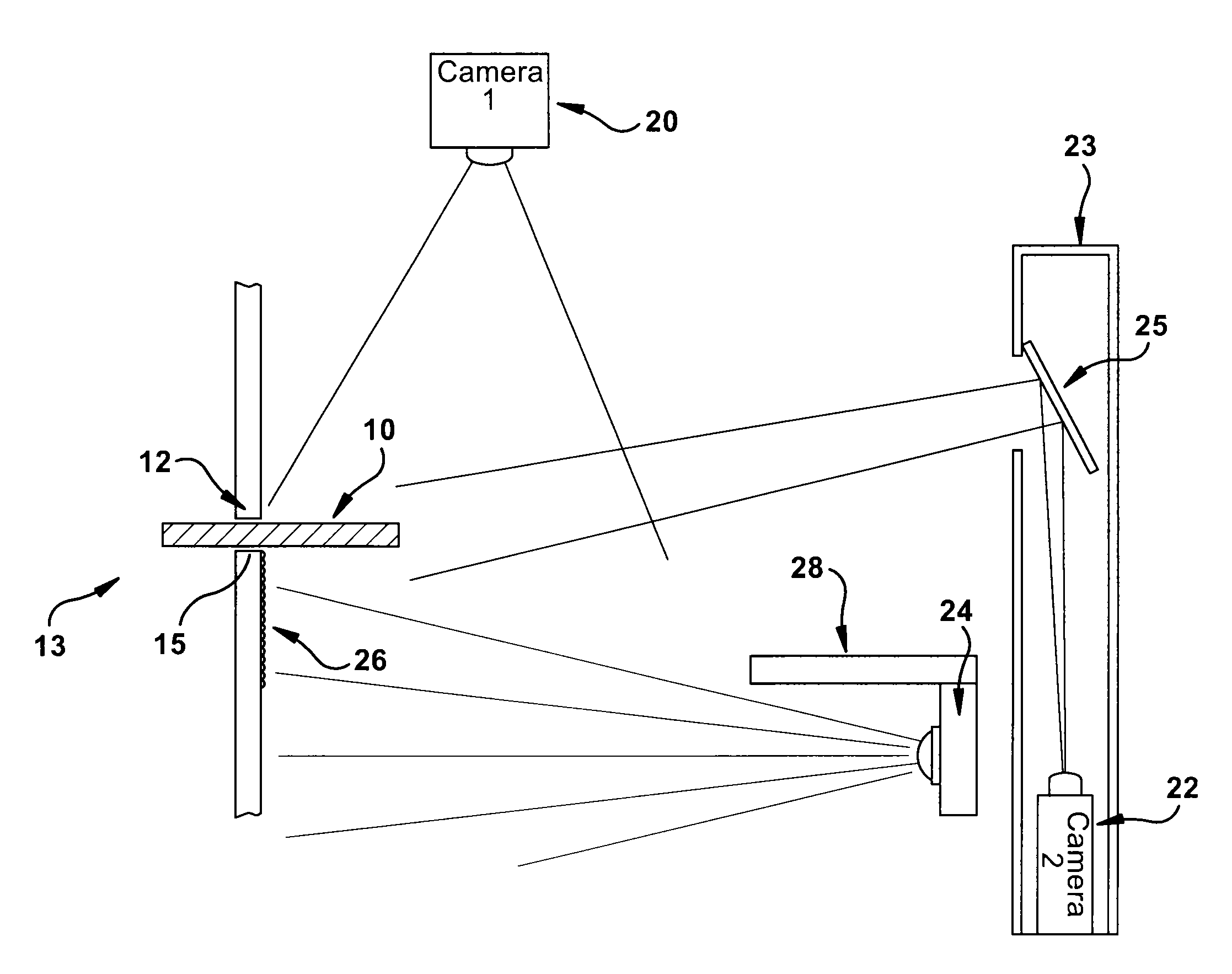
A key identification system is provided. The key identification system comprises an imaging system to capture an image of a master key, and a logic to analyze the captured image. The imaging system may be capture an image of a groove in the master key from an angle between perpendicular and parallel to the blade of said master key. The logic analyzes the captured image to compare characteristics of the groove with groove characteristics of known key blanks to determine the likelihood of a match between the master key and a known key blank. The key identification system may further compensate for displacement or orientation of the master key with respect to the imaging system when analyzing characteristics of the groove.

Description

CROSS-REFERENCE TO RELATED APPLICATIONS[0001]This application claims the benefit of priority of U.S. Provisional Patent Application Ser. No. 61 / 215,152 filed on May 1, 2009, and U.S. Provisional Patent Application Ser. No. 61 / 275,654 filed on Sep. 1, 2009, each of which are hereby incorporated by reference in their entirety.FIELD OF ART[0002]This invention relates generally to the field of systems for identifying objects and, more particularly to systems for utilizing electronic means for identifying key blanks that are compatible with an unknown key.BACKGROUND OF THE INVENTION[0003]The art of key replication is well known. Commonly, a key intended for duplication (the master key) is copied on to an appropriately identified key blank utilizing any number of different systems known in the art. The process of identifying an appropriate key blank to use when making copies of a key can be a difficult, tedious and time consuming affair. It is important that each master key be copied onto...

Claims


Application Information

Patent Timeline
Patent Type & Authority Patents(United States)
IPC IPC(8): G06K9/00G06K9/62B23C1/16B23C1/18G06V10/147G06V10/46H04N23/90
CPCB23C2235/41G06K9/48G06K9/209G06K9/00208G06T7/602G06K9/6202G06T7/62Y10T409/300952Y10T409/301064Y10T409/301008G06V20/647G06V10/147G06V10/46G06V20/66H04N23/90B23C3/35B23C2235/12G06T2207/10141
Inventor THOMPSON, CHESTER O. D.MUTCH, WILLIAM R.
Owner HY KO PRODS
Learn More