
Bottle cleaning machine

a cleaning machine and bottle body technology, applied in the direction of cleaning process and equipment, cleaning process using liquids, chemistry apparatus and processes, etc., can solve the problems of saving cycle time, energy and water, and intensive mechanical cleaning, and achieve the effect of less expensive cleaning operation

Inactive Publication Date: 2014-02-04
KRONES AG
View PDF15 Cites 2 Cited by
  • Summary
  • Abstract
  • Description
  • Claims
  • Application Information

AI Technical Summary

Benefits of technology

[0004]Starting therefrom, it is the object of the present disclosure to provide a simplified bottle cleaning machine and a simplified method for cleaning bottles, which permit a more efficient, more eco-friendly and less expensive cleaning operation.
[0005]In contrast to the prior at the bottles to be cleaned are no longer passed through caustic immersion baths, but are transported along a substantially spiral transportation path past the spraying nozzles. Spiral substantially means here that spiral need not be an exactly mathematical spiral, but that the transportation path is winding around a central axis. Since the bottles are transported in spiral form past the spraying nozzles, the bottles can be cleaned intensively in a mechanical way by means of the spraying nozzles. This intensive mechanical cleaning saves cycle time, energy and water. In comparison with the prior art a substantially smaller amount of caustic solution is needed. The smaller caustic amount entails the following advantages:
[0006]a lot of weight is saved, resulting in less “steel and iron”;

Problems solved by technology

This intensive mechanical cleaning saves cycle time, energy and water.

Method used


Image

  • Bottle cleaning machine
  • Bottle cleaning machine
  • Bottle cleaning machine

Examples


Embodiment Construction

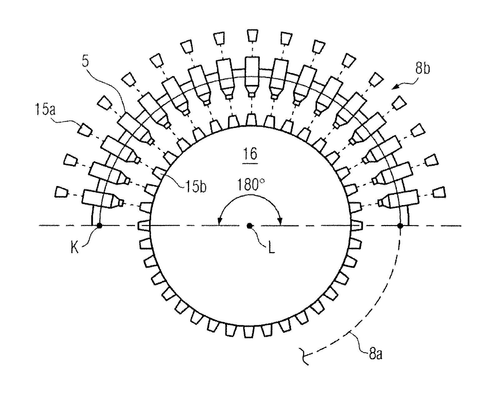
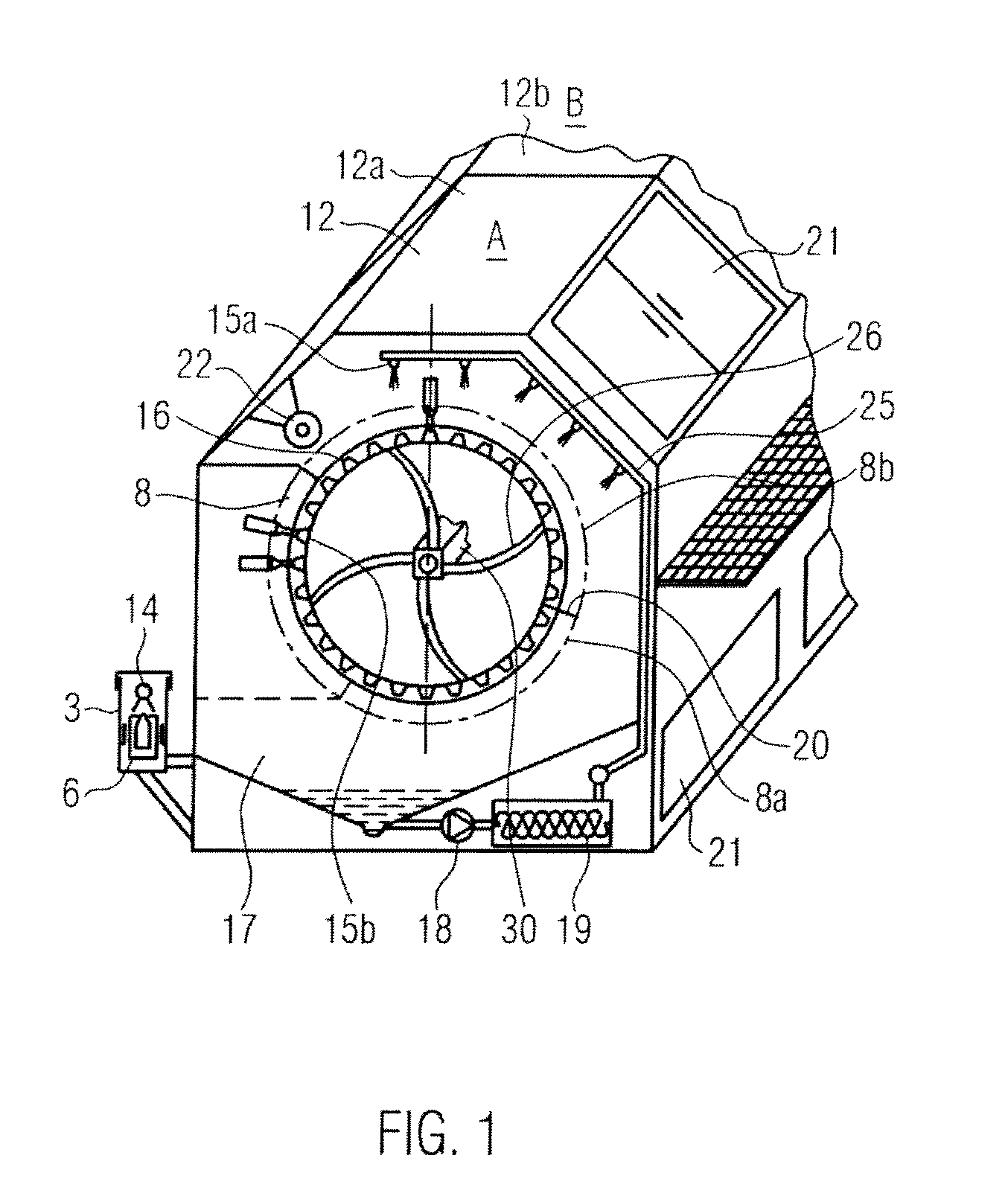
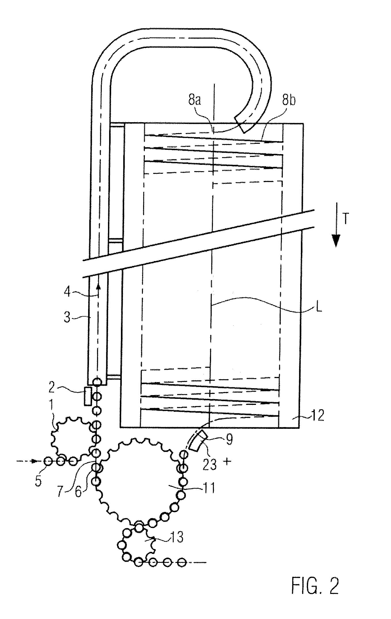
[0027]FIG. 1 is a schematic illustration showing a section of a bottle cleaning machine according to the present disclosure. FIG. 2 shows across section through the bottle cleaning machine 10 according to the disclosure. The bottle cleaning machine 10 comprises a bottle transporting device for transporting the bottles 5 to be cleaned, which device is configured such that the bottles 5 are transported past spraying nozzles 15a, b along a substantially spiral transportation path. The bottles 5 are here held with bottle holders 6 so that the bottles can also be moved overhead and the mouthpiece of the bottle is centered in the middle. The bottle holders are interconnected via a corresponding joint 40 (FIG. 4b) to form a room-traveling chain 7. Especially the bottle baskets 6 as shown in FIGS. 4a, 4b are suited as bottle holders.

[0028]The bottles 5 are accommodated in the bottle baskets 6 and are retained e.g. via a pivotable basket lid 41, through which the bottle neck projects for exa...


PUM


Abstract

A bottle cleaning machine and to a method for cleaning bottles with a bottle transporting device for transporting the bottles to be cleaned and with spraying nozzles. The bottle transporting device is configured such that the bottles are transported past the spraying nozzles along a substantially spiral transportation path, and preferably about a horizontal axis.

Description

CROSS-REFERENCE TO RELATED APPLICATION[0001]The present application claims the benefit of priority of German Application No. 102009008724.9, filed Feb. 12, 2009. The entire text of the priority application is incorporated herein by reference in its entirety.FIELD OF THE DISCLOSURE[0002]The present disclosure relates to a bottle cleaning machine and to a method for cleaning bottles.BACKGROUND[0003]The classic bottle cleaning machines known from the prior art (e.g. LAVATEC of the company KRONES, the assignee of the present application) move the bottles in bottle containers, which are arranged in a row on crossbars, through the different caustic baths. FIG. 6 shows, for instance, the sections that are arranged one after the other and through which a bottle is passed to be cleaned. The caustic baths must have a certain volume to achieve the corresponding treatment times and adequate cleaning. The large volume, however, means a lot of chemicals, a lot of energy for heating and for mainta...

Claims


Application Information

Patent Timeline
Patent Type & Authority Patents(United States)
IPC IPC(8): B08B3/00
CPCB08B9/42B08B9/30B08B9/34
Inventor GMEINER, FRANZ
Owner KRONES AG
Learn More