Method for generating images with an expanded dynamic range and optical device for carrying out such a method, in particular a laser scanner microscope

a laser scanner and dynamic range technology, applied in the field of laser scanner microscopes, can solve the problems of insufficient signal-to-noise ratio (snr), poor contrast, and heterogeneous distribution of concentration in the samples to be examined, and achieve the effects of increasing the dynamic range, improving signal, and increasing laser intensity

Active Publication Date: 2014-01-21
CARL ZEISS MICROSCOPY GMBH
View PDF15 Cites 3 Cited by
  • Summary
  • Abstract
  • Description
  • Claims
  • Application Information

AI Technical Summary

Benefits of technology

[0017]The range-individual (preferably pixel-individual) selection from the different signal evaluations using one or more result signals makes it possible to use the signal evaluation with the dynamic range optimal for the sample range concerned for different image elements. As a consequence, the resulting image receives an expanded dynamic range that results from the combined amount of the (narrower) dynamic ranges of the individual image elements. The total noise in the image to be generated can therefore be reduced by pixel noise minimization to the noise of the particular lowest noise acquisition method / evaluation method. A time-consuming sequential acquisition of several individual images can be eliminated. Only a single optoelectronic detector is required whose total dynamic range can be utilized.
[0027]Also, a series of images with a dynamic range expanded in accordance with the invention and with different integration times or excitation light intensities can be acquired and combined to an HDR image. For example, in such an embodiment instead of a selection of the evaluation channel by pixels the channel selection can also take place for entire individual images that are subsequently combined by pixels to a dynamically expanded image. Then, for example, individual images with short integration times are completely processed in an evaluation channel with single photon counting; SPC and individual images with longer integration times are processed in an oversampling channel. In an alternative embodiment the excitation intensity as well as the exposure time can be modified simultaneously or sequentially for expanding the dynamic range. To this end the individual pixels can be evaluated as regards their signal quality. If, for example, the measuring with a very long integration time in a pixel did not generate a good signal, an additional measuring with a higher laser intensity can produce a better signal and thus contribute to the expansion of the dynamic range.

Problems solved by technology

Microscopic examinations with fluorescent dyes result in many instances in heterogeneous distributions of concentration in the samples to be examined.
However, as a consequence dark image areas (with low average light intensities) are recorded only with insufficient signal-to-noise ratio (SNR), that is, with poor contrast.
Inversely, a longer exposure time does make possible the contrast-rich photographing of dark image areas but results in an overcontrol (low contrast) of the bright image areas.
However, the sequential acquisition of several individual images is expensive and slow.
In particular, it is problematic in the observation of fluorescence since the intensity of the fluorescence changes between the acquisitions by the fading of the fluorophones.
Especially in the case of living samples the multiple acquisition results in a high beam load, especially in the case of scanning methods such as in laser scanning microscopy.
In addition, the sequential acquisition is not suitable for the observation of dynamic operating sequences.
This can limit the possible evaluation methods or lead to increased expenses for the reduction of error recognition.
In addition, the determination of the boundary frequencies of the high pass / low pass combination necessary for the development time renders difficult the adaptation to new applications or detection methods during the service life of the device.
Moreover, the high pass / low pass combination leads to non-linear amplitudes and phase distortions that can have a disadvantageous effect in particular in frequency area methods (Engl.
However, this obligatorily requires a division of the light signal onto several channels and several optoelectronic detectors that represent additional noise sources.

Method used


Image

  • Method for generating images with an expanded dynamic range and optical device for carrying out such a method, in particular a laser scanner microscope
  • Method for generating images with an expanded dynamic range and optical device for carrying out such a method, in particular a laser scanner microscope
  • Method for generating images with an expanded dynamic range and optical device for carrying out such a method, in particular a laser scanner microscope

Examples


Embodiment Construction

[0036]In describing preferred embodiments of the present invention illustrated in the drawings, specific terminology is employed for the sake of clarity. However, the invention is not intended to be limited to the specific terminology so selected, and it is to be understood that each specific element includes all technical equivalents that operate in a similar manner to accomplish a similar purpose.

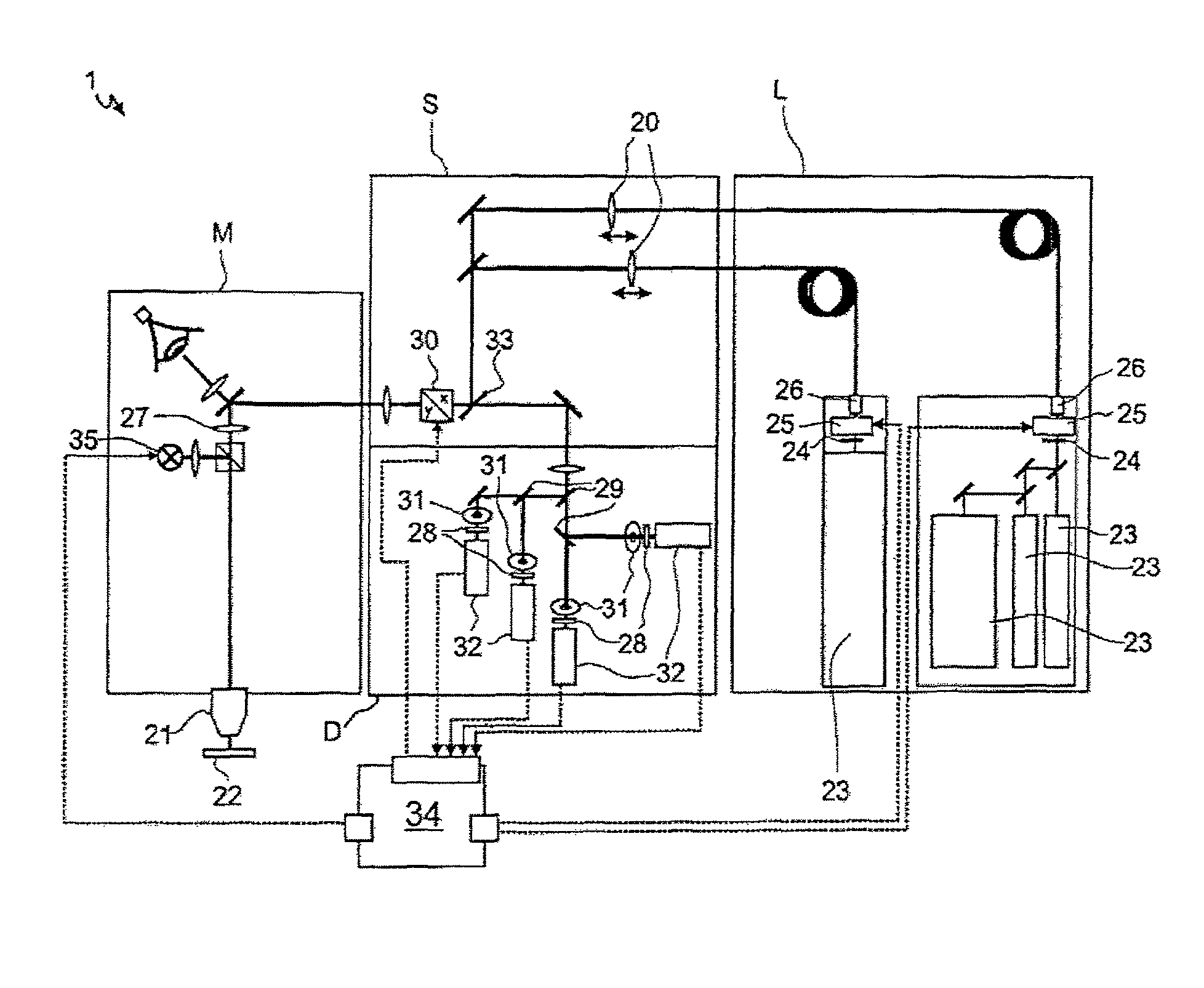
[0037]FIG. 1 schematically shows a laser scanning microscope 1 whose control unit 34 is arranged for carrying out the method in accordance with the invention. The LSM 1 is composed in a modular manner from an exposure module L with lasers 23, a scanning module S, a detection module D and the microscope unit M with the microscope lens 21.

[0038]The light of the laser 23 can be influenced by light flaps 24 and attenuators 25, for example, an acusto-optically tunable filter; AOTF of the control unit 34 before it is fed via optical fibers and coupling lenses 20 into the scanning unit S and com...


PUM


Abstract

Method and apparatus for generating an at least two-dimensional image of at least part of a sample. The method involves scanning the sample. Acquiring at least one light signal by an optoelectronic detector for different areas of the sample. Converting the light signal into an electrical signal. Distributing the electrical signal onto several parallel evaluation channels whose signal evaluations differ from each other so that their dynamic ranges are different. Generating a result signal in each evaluation channel. Selecting at least one of the result signals as a function of one of the result signals in order to generate the image for the sample range concerned. It is also possible to generate one intermediate result signal for each channel, typically from the respective actual result signal and one or more other sources. Thus the signal selection depending on both the result signals and the intermediate result signals are possible.

Description

CROSS-REFERENCE TO RELATED APPLICATIONS[0001]The present patent application is a Continuation of International Application No. PCT / EP2010 / 005263 filed Aug. 27, 2010, published in German, which is based on, and claims priority from, German Application No. 10 2009 043 746.0, filed Sep. 30, 2009, both of which are incorporated herein by reference in their entireties.BACKGROUND OF THE INVENTION[0002]1. Field of the Invention[0003]The invention relates to a method for generating an at least two-dimensional image of at least a part of a sample. The optical devices can be, for example, telescopes, microscopes, material-testing devices and other analyzing devices. The origin of the light is inconsequential, so that the invention can serve, for example, in conjunction with scintillation for the detection of ionizing radiation. However, the invention is preferably used for the detection of fluorescence.[0004]2. Related Art[0005]Microscopic examinations with fluorescent dyes result in many ins...

Claims


Application Information

Patent Timeline
Patent Type & Authority Patents(United States)
IPC IPC(8): H01L27/00
CPCG01J1/42G01J1/20G02B21/008
Inventor MOHLER, GUNTERSCHMIDT, DIETMARHOLUB, OLIVER
Owner CARL ZEISS MICROSCOPY GMBH
Why Eureka
Try Eureka