
Faucet structure

a faucet and structure technology, applied in the field of faucet structure, can solve the problems of high manufacturing cost, inconvenient adjustment for users, and easy failure of manufacturing process, and achieve the effect of simplifying the structure of the main body, simplifying the manufacturing process, and reducing the complexity of the main body

Inactive Publication Date: 2014-01-21
DA YUAN SHENG IND
View PDF3 Cites 14 Cited by
  • Summary
  • Abstract
  • Description
  • Claims
  • Application Information

AI Technical Summary

Benefits of technology

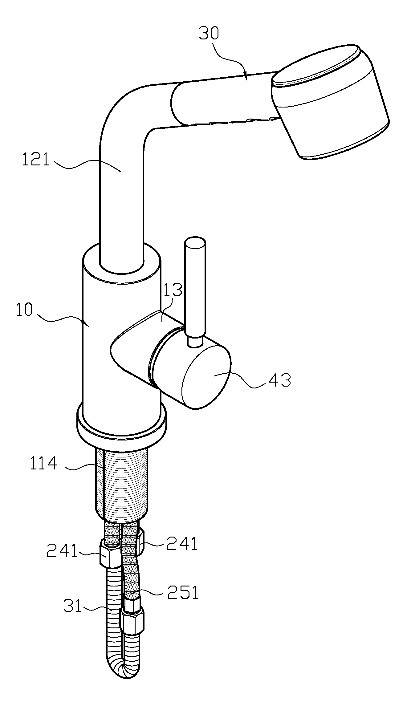
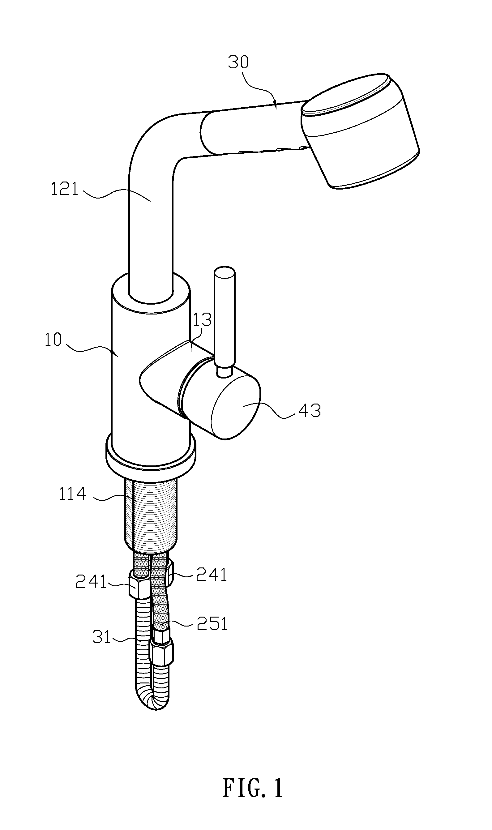
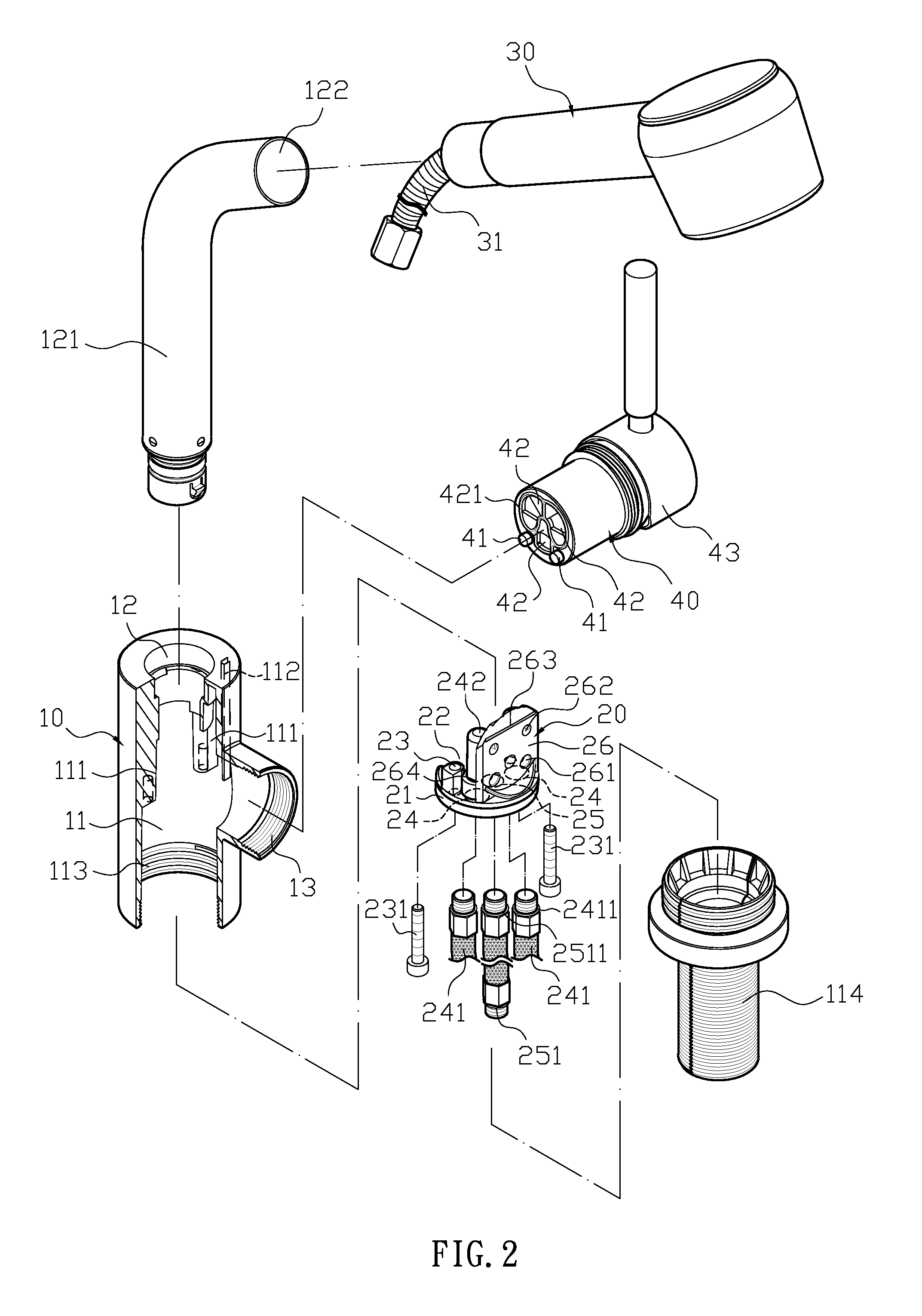
The present invention provides a faucet structure that includes a main body, a water collecting base, a water output head, and a water control valve. The main body is tubular with thin body wall and has a receiving space with a downward opening. The water collecting base has a recessed opening and a through hole with locking unit to lock the engaging post of the main body. The faucet also has water inlet and outlet channels with positioning holes and flow holes. The water output head is connected to the water inlet channel through a bendable extension tube. The water control valve is connected to the water collecting base and has three openings and two positioning posts that plug into the positioning holes of the water collecting base. The faucet structure is advantageous in that it reduces complexity, simplifies manufacturing process, avoids interference during installation, and allows for easy assembly and disassembly of the main body and connecting body.

Problems solved by technology

Also, the manufacturing process becomes more complicated and is easy to fail, so the manufacturing cost is high; (b) the receiving space of the faucet body is too narrow, so it is difficult and inconvenient for the user to adjust and align water inter / outlet tubes with the flow holes of the valve slot; and (c) the faucet body of the faucet and the connecting portion are often made in one piece, it is difficult to assemble or disassemble.
So, if the manufacturer wants to promote different types of faucets, the user has to change the entire set (including the faucet body and connecting portion), which is not cost-effective.

Method used


Image

  • Faucet structure
  • Faucet structure
  • Faucet structure

Examples


Embodiment Construction

[0015]The detailed description set forth below is intended as a description of the presently exemplary device provided in accordance with aspects of the present invention and is not intended to represent the only forms in which the present invention may be prepared or utilized. It is to be understood, rather, that the same or equivalent functions and components may be accomplished by different embodiments that are also intended to be encompassed within the spirit and scope of the invention.

[0016]Unless defined otherwise, all technical and scientific terms used herein have the same meaning as commonly understood to one of ordinary skill in the art to which this invention belongs. Although any methods, devices and materials similar or equivalent to those described can be used in the practice or testing of the invention, the exemplary methods, devices and materials are now described.

[0017]All publications mentioned are incorporated by reference for the purpose of describing and disclos...


PUM


Abstract

A faucet structure includes a main body, a water collecting base, a water output head and a water control valve. The main body is tubular with thin body wall, having a receiving space that receives the water collecting base having two water inlet holes and one water outlet hole on lower portion thereof, and a water inlet channel and a water outlet channel extends from the water inlet hole and water outlet hole. A valve base is formed on sideway of the water inlet channel and the water outlet channel. The faucet includes the main body and the water collecting base respectively, so the complexity of the main body is reduced, and the manufacturing process is simplified. Also, the structure of the main body can be simplified to a thin-wall structure to reduce material and further reduce manufacturing costs.

Description

FIELD OF THE INVENTION[0001]The present invention relates to an improved faucet structure, and more specifically to the faucet including a main body and a water collecting base respectively to reduce the complexity of the main body, and further simplify the manufacturing process. Also, the structure of the main body can be simplified to a thin-wall structure to reduce material, and further reduce manufacturing costs.BACKGROUND OF THE INVENTION[0002]In conventional faucets, the water output position is usually fixed and the water output distance cannot be easily adjusted, so the user can only use the containers to collect water when he / she wants to wash the floor or vegetables, which is inconvenient in use. Due to the restriction of the faucet stated above, a pullable faucet is presented. The base of the faucet body extends downwards to connect with the connecting portion and a receiving space is formed. A valve slot for water control valve is recessedly formed on an upper portion of...

Claims


Application Information

Patent Timeline
Patent Type & Authority Patents(United States)
IPC IPC(8): E03C1/04F16K5/00F15B13/00B05B1/30B05B9/03
CPCF16K51/00E03C2001/0415Y10T137/9464Y10T137/6014F16K27/06E03C1/04
Inventor HSU, MING-YUAN
Owner DA YUAN SHENG IND
Learn More