
Over-purlin insulation system for a roof

a technology of roof insulation and purlin, which is applied in the direction of roof, building repair, walls, etc., can solve the problems of reducing the thermal resistance of degrading the insulation properties of the roof insulation system, and compromising the thermal resistance of the insulation

Inactive Publication Date: 2014-01-14
BLUESCOPE BUILDINGS NORTH AMERICA
View PDF26 Cites 12 Cited by
  • Summary
  • Abstract
  • Description
  • Claims
  • Application Information

AI Technical Summary

Benefits of technology

The system effectively maintains the thermal resistance of the insulation by creating insulation receiving areas between purlins, preventing compression and thus preserving the insulation properties.

Problems solved by technology

The thermal resistance offered by the insulation is compromised when it is compressed or packed down.
In conventional metal roof insulation systems, when the roof structure is applied to the tops of the roof purlins, the thick layer of blanket insulation is compressed, thus reducing the thermal resistance of the roof insulation system.
In some areas of the conventional roof system, the compression of the insulation is so severe that a thermal short is created, thus substantially degrading the insulation properties of the roof insulation system.

Method used


Image

  • Over-purlin insulation system for a roof
  • Over-purlin insulation system for a roof
  • Over-purlin insulation system for a roof

Examples


Embodiment Construction

[0013]The present disclosure provides systems and methods for providing insulation for a metal roof, according to various embodiments.

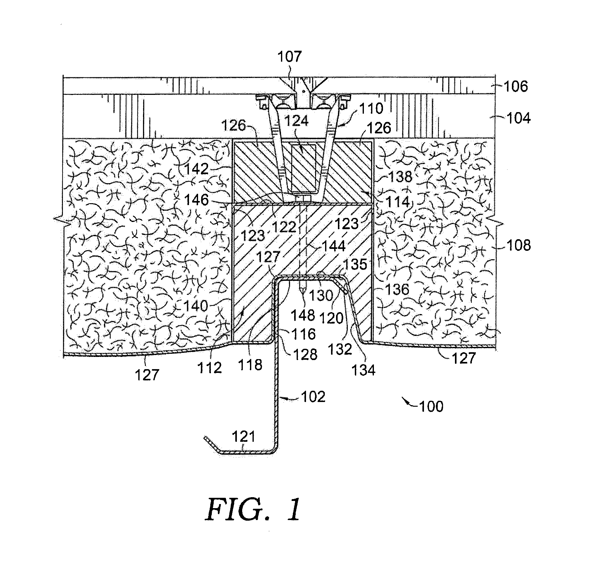
[0014]According to one aspect, a system 100 according to the disclosure includes a thermal block arrangement which is mountable on a plurality of parallel purlins as part of a roofing system. The arrangement is depicted in FIGS. 1-2. FIG. 1 illustrates a cross-sectional view of the system 100 taken from a plane perpendicular to a longitudinal purlin. Although the system can be used with different kinds of purlins (e.g., C-shaped and other varieties), the purlin 102 shown in FIGS. 1-2 is Z-shaped and is, therefore, referred to as a Z-purlin. Z-purlins typically have a vertical web portion 116 and a horizontal top 118. The horizontal top 118 has a downwardly sloped front lip 120. The bottom portion 121 of purlin 102 has a similarly-shaped configuration that extends in an opposite direction from the direction of the top portion 118.

[0015]System 100 enabl...


PUM


Abstract

A system and method for insulating a metal roof includes a thermal block arrangement disposed over each of a pair of purlins. A vapor-barrier sheet spans between and is secured over the opposing pair of purlins, the vapor-barrier sheet being secured underneath each thermal block arrangement. A batt insulation receiving cavity is defined by an upper surface of the vapor-barrier sheet and between opposing faces of each of the thermal block arrangements.

Description

CROSS-REFERENCE TO RELATED APPLICATIONS[0001]This application claims the benefit of U.S. Provisional Application No. 61 / 413,647 filed Nov. 15, 2010, the disclosure of which is incorporated herein by reference.BACKGROUND OF THE INVENTION[0002]1. Field of the Invention[0003]The invention relates generally to the field of roof structures and related methods. More specifically, the invention relates to the field of insulating metal roofing structures.[0004]2. Description of the Related Art[0005]Roof insulation has been used in metal building arrangements. A typical roof insulation configuration uses blanket insulation. The thermal resistance offered by the insulation is compromised when it is compressed or packed down. In conventional metal roof insulation systems, when the roof structure is applied to the tops of the roof purlins, the thick layer of blanket insulation is compressed, thus reducing the thermal resistance of the roof insulation system. In some areas of the conventional ro...

Claims


Application Information

Patent Timeline
Patent Type & Authority Patents(United States)
IPC IPC(8): E04B1/74
CPCE04D13/1618E04D3/364
Inventor MCCLURE, RICHARD, R.
Owner BLUESCOPE BUILDINGS NORTH AMERICA
Learn More