Eureka AIR delivers breakthrough ideas for toughest innovation challenges, trusted by R&D personnel around the world.

Systems and methods for parallax detection and correction in images captured using array cameras that contain occlusions using subsets of images to perform depth estimation

a technology of array cameras and parallax detection, applied in the field of digital cameras, can solve the problems of increasing the prevalence of partially occluded regions (pixels visible in some but not all images), and it is difficult to simultaneously capture the collection of 2d images of a scene that form a light field. it can reduce the weighting applied

Active Publication Date: 2013-12-31
FOTONATION LTD
View PDF137 Cites 456 Cited by
  • Summary
  • Abstract
  • Description
  • Claims
  • Application Information

AI Technical Summary

Benefits of technology

The patent text describes a method for reducing the weighting applied to different color channels in an image based on the estimated signal-to-noise ratio (SNR) at different pixel locations. This helps to improve the overall quality of the image. The method also involves estimating the cost of a disparity search over a desired depth range to optimize the image processing. The technical effects of this patent make it easier to produce high-quality images and videos.

Problems solved by technology

Due to practical constraints, it is typically difficult to simultaneously capture the collection of 2D images of a scene that form a light field.
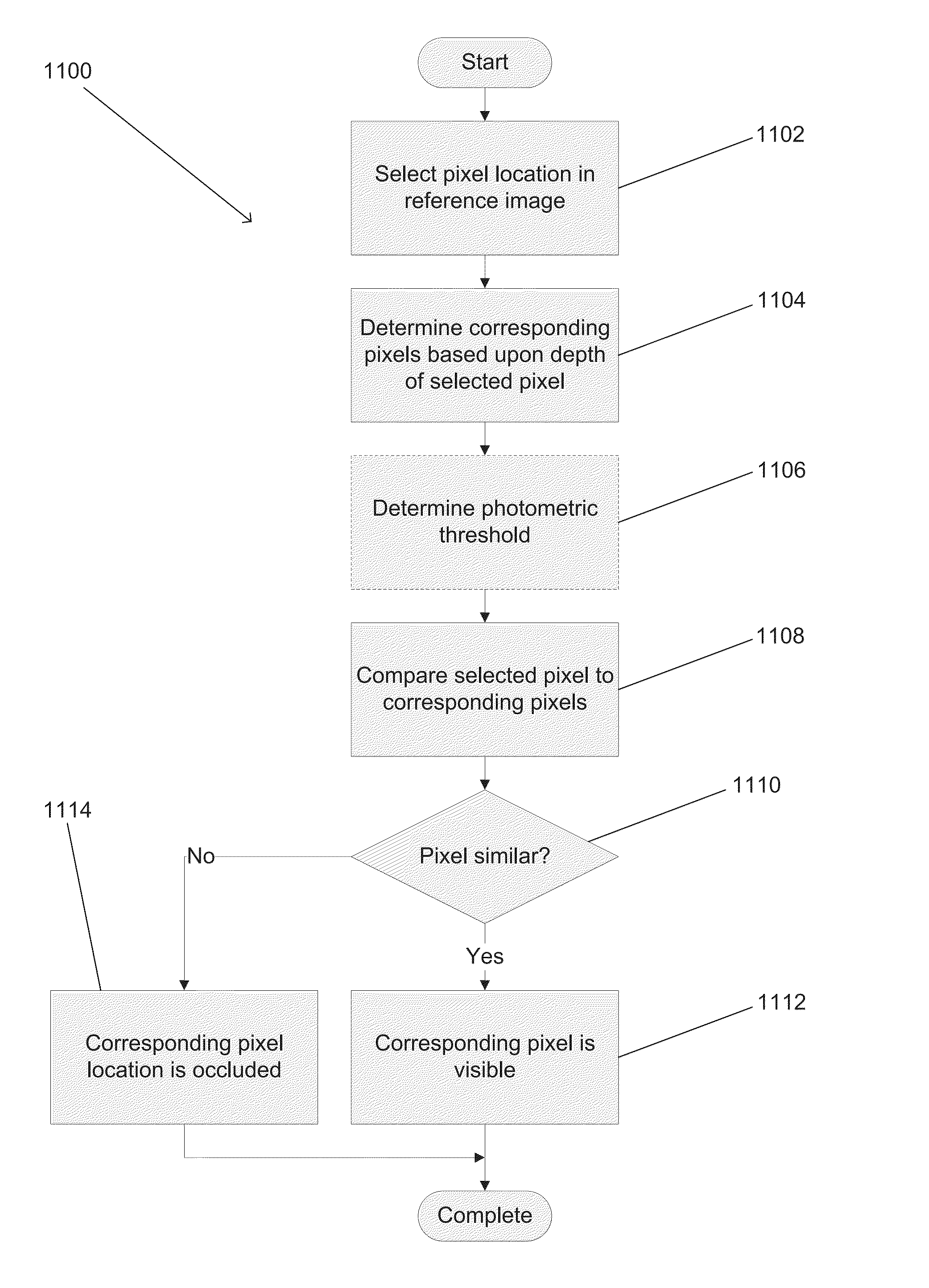
The challenge, as more images are added, is that the prevalence of partially occluded regions (pixels visible in some but not all images) also increases.

Method used


Image

  • Systems and methods for parallax detection and correction in images captured using array cameras that contain occlusions using subsets of images to perform depth estimation
  • Systems and methods for parallax detection and correction in images captured using array cameras that contain occlusions using subsets of images to perform depth estimation
  • Systems and methods for parallax detection and correction in images captured using array cameras that contain occlusions using subsets of images to perform depth estimation

Examples


Embodiment Construction

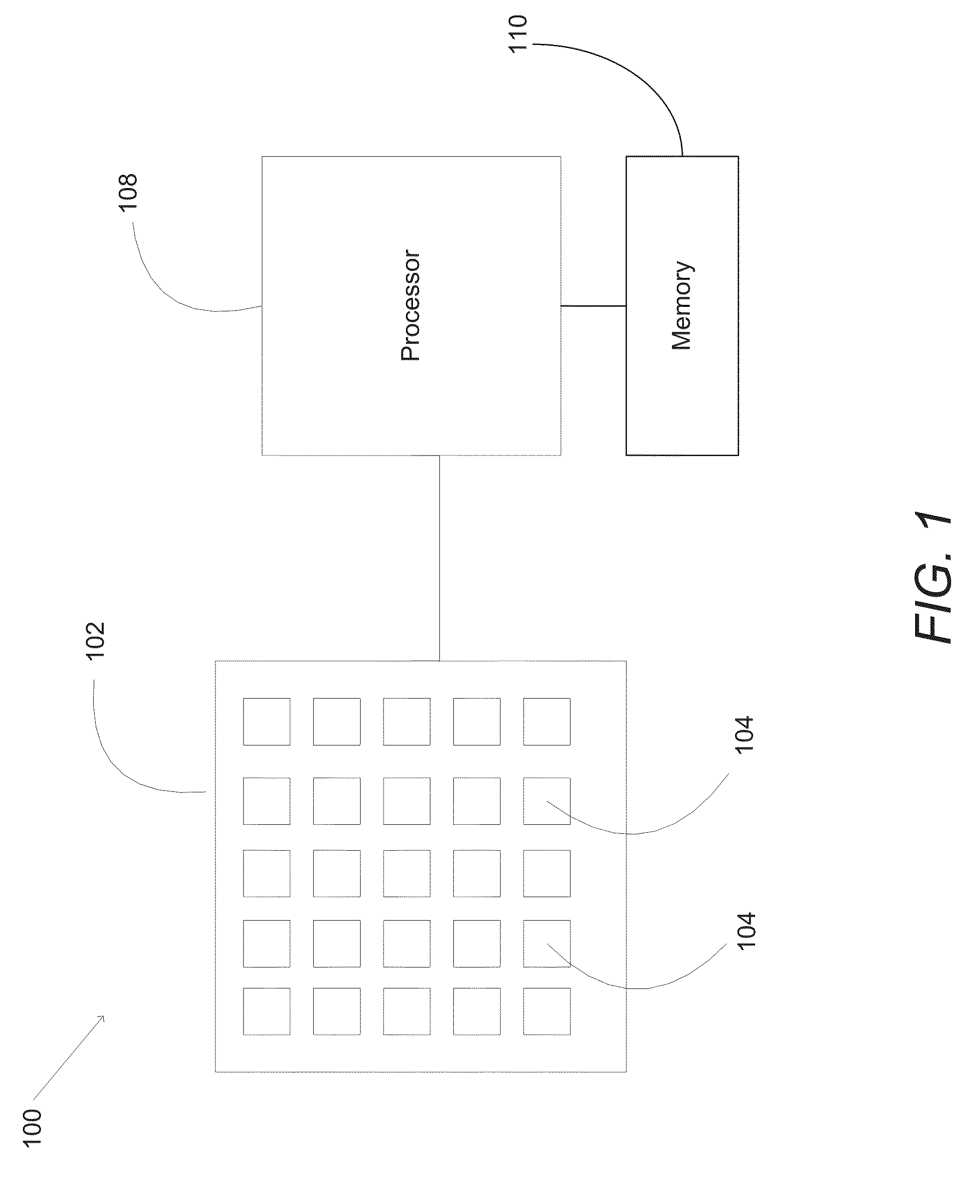
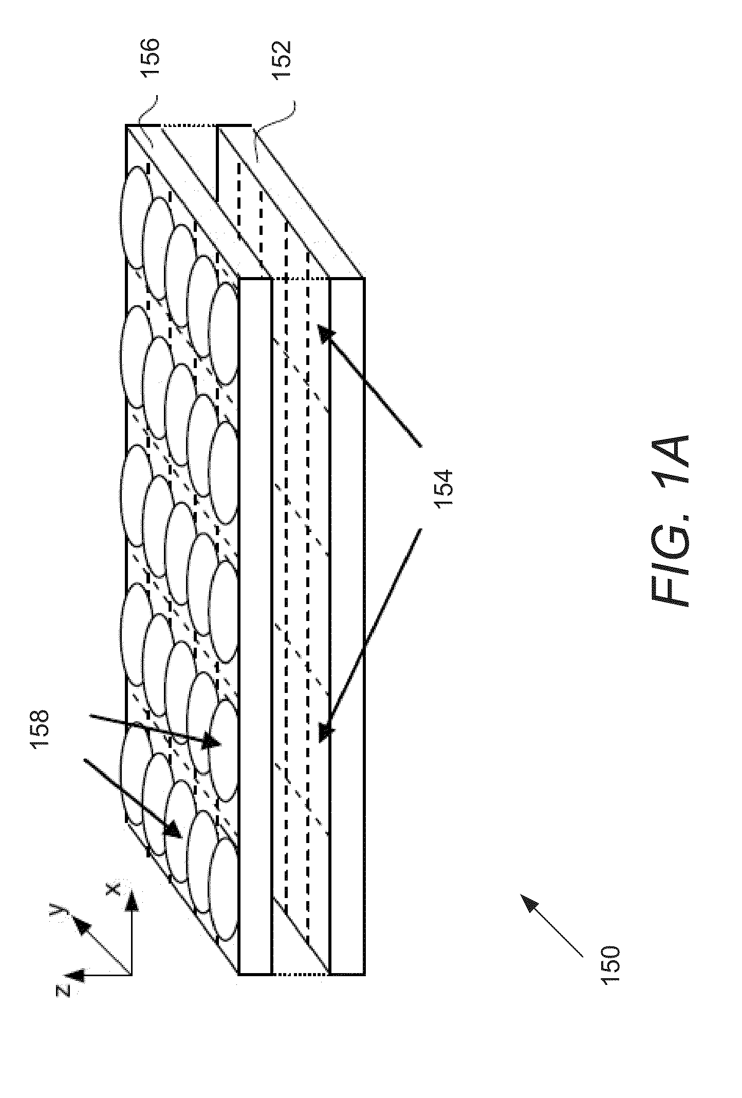
[0146]Turning now to the drawings, systems and methods for parallax detection and correction in images captured using array cameras are illustrated. Array cameras, such as those described in U.S. patent application Ser. No. 12 / 935,504 entitled “Capturing and Processing of Images using Monolithic Camera Array with Heterogeneous Imagers” to Venkataraman et al., can be utilized to capture light field images. In a number of embodiments, super-resolution processes such as those described in U.S. patent application Ser. No. 12 / 967,807 entitled “Systems and Methods for Synthesizing High Resolution Images Using Super-Resolution Processes” to Lelescu et al., are utilized to synthesize a higher resolution 2D image or a stereo pair of higher resolution 2D images from the lower resolution images in the light field captured by an array camera. The terms high or higher resolution and low or lower resolution are used here in a relative sense and not to indicate the specific resolutions of the imag...


PUM


Abstract

Systems in accordance with embodiments of the invention can perform parallax detection and correction in images captured using array cameras. Due to the different viewpoints of the cameras, parallax results in variations in the position of objects within the captured images of the scene. Methods in accordance with embodiments of the invention provide an accurate account of the pixel disparity due to parallax between the different cameras in the array, so that appropriate scene-dependent geometric shifts can be applied to the pixels of the captured images when performing super-resolution processing. In several embodiments, detecting parallax involves using competing subsets of images to estimate the depth of a pixel location in an image from a reference viewpoint. In a number of embodiments, generating depth estimates considers the similarity of pixels in multiple spectral channels. In certain embodiments, generating depth estimates involves generating a confidence map indicating the reliability of depth estimates.

Description

CROSS-REFERENCE TO RELATED APPLICATIONS[0001]The current application claims priority to U.S. Provisional Patent Application Ser. No. 61 / 691,666 to Venkataraman et al. entitled “Systems and Methods for Parallax Detection and Correction in Images Captured using Array Cameras”, filed Aug. 21, 2012 and U.S. Provisional Patent Application Ser. No. 61 / 780,906 to Venkataraman et al. entitled “Systems and Methods for Parallax Detection and Correction in Images Captured using Array Cameras”, filed Mar. 13, 2013. The disclosures of U.S. Provisional Patent Application Ser. Nos. 61 / 691,666 and 61 / 780,906 are hereby incorporated by reference herein in their entirety.FIELD OF THE INVENTION[0002]The present invention generally relates to digital cameras and more specifically to the detection and correction of parallax in images captured using array cameras.BACKGROUND[0003]Binocular viewing of a scene creates two slightly different images of the scene due to the different fields of view of each eye...

Claims


Application Information

Patent Timeline
IPC IPC(8): G06T15/10G06K9/00H04N13/232
CPCG06T7/0065G06T15/20G06T2200/21G02B27/0075G06T2207/10052H04N13/0232G06K9/00H04N5/23212H04N13/0022G06T7/0075H04N9/097G03B35/08G06T15/10G06T2207/10024G06T2207/10012G06T7/002H04N13/0242H04N13/232H04N13/243H04N2013/0088H04N2013/0081G06T7/85G06T7/557G06T7/593G06T7/55H04N13/128H04N23/16
Inventor CIUREA, FLORIANVENKATARAMAN, KARTIKMOLINA, GABRIELLELESCU, DAN
Owner FOTONATION LTD
Why Eureka
Eureka Blog
Learn More