
Method and system for optimizing bandwidth usage in remote visualization

a bandwidth utilization and visualization technology, applied in the field of remote visualization, can solve the problems of bandwidth saturation and lower throughput for each connected end-station, and achieve the effects of high update frequency, low image quality, and high image quality

Active Publication Date: 2013-12-10
LENOVO GLOBAL TECH INT LTD
View PDF10 Cites 32 Cited by
  • Summary
  • Abstract
  • Description
  • Claims
  • Application Information

AI Technical Summary

Benefits of technology

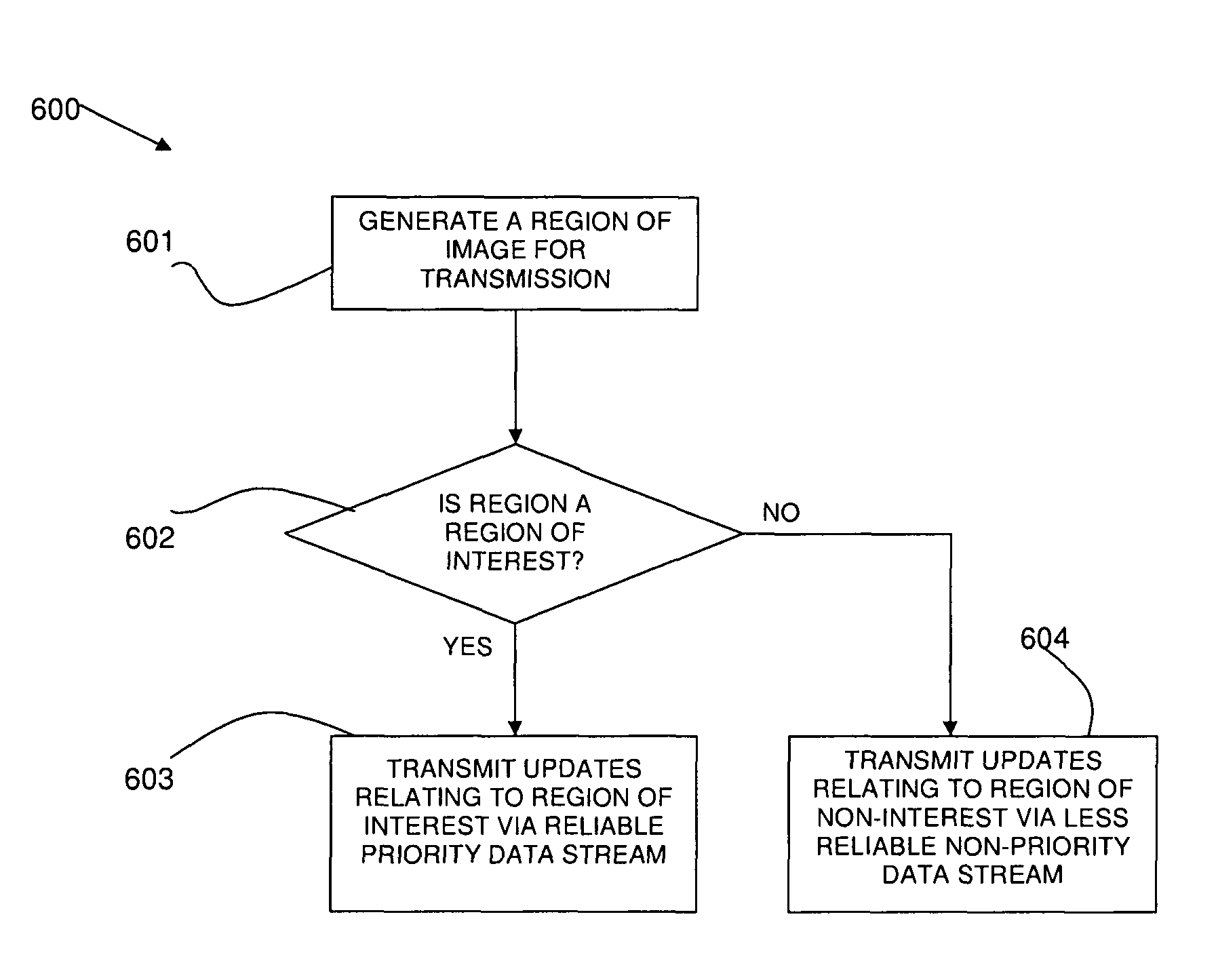
The patent describes a method for sending different regions of an image using two different transmission protocols. The first protocol is used for important regions that require high quality and frequent updates, while the second protocol is used for less important regions that can have lower quality and less frequent updates. This allows for efficient use of bandwidth and ensures that all parts of the image are sent quickly and accurately.

Problems solved by technology

One major limitation of all of these known approaches is bandwidth saturation.
As the number of end-stations or the number of required data updates increases, network bandwidth resources become saturated with such updates, resulting in a lower throughput for each connected end-station.

Method used


Image

  • Method and system for optimizing bandwidth usage in remote visualization
  • Method and system for optimizing bandwidth usage in remote visualization
  • Method and system for optimizing bandwidth usage in remote visualization

Examples


Embodiment Construction

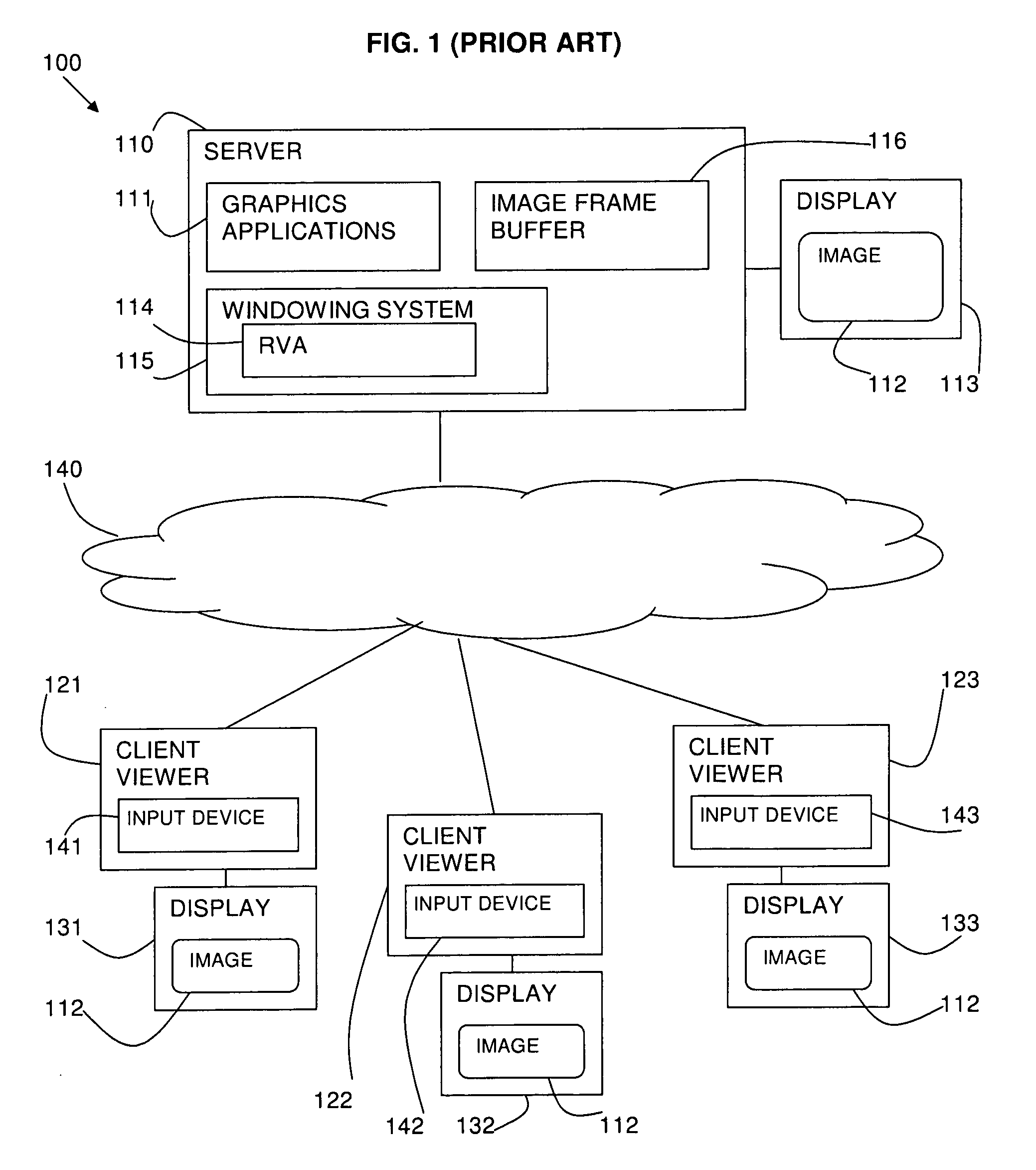
[0024]Referring to FIG. 1, a remote visualization system 100 is provided as known in the prior art. A server system 110 is provided on which a plurality of graphics applications 111 are executed. The plurality of graphics applications 111 generate an image 112 on a server display 113.

[0025]A plurality of remote client systems (i.e., client viewers) 121, 122, and 123 are connected to the server system 110 via a network 140. The remote client systems 121, 122, and 123 respectively comprise local client displays 131, 132, and 133 and input devices 141, 142, and 143. The remote client systems 121, 122, and 123 can view the server image 112 on the respective local client displays 131, 132, and 133. A remote client system 121, 122, 123 can interact with the plurality of server graphics applications 111 on the client display 131, 132, 133 via the input device 141, 142, 143.

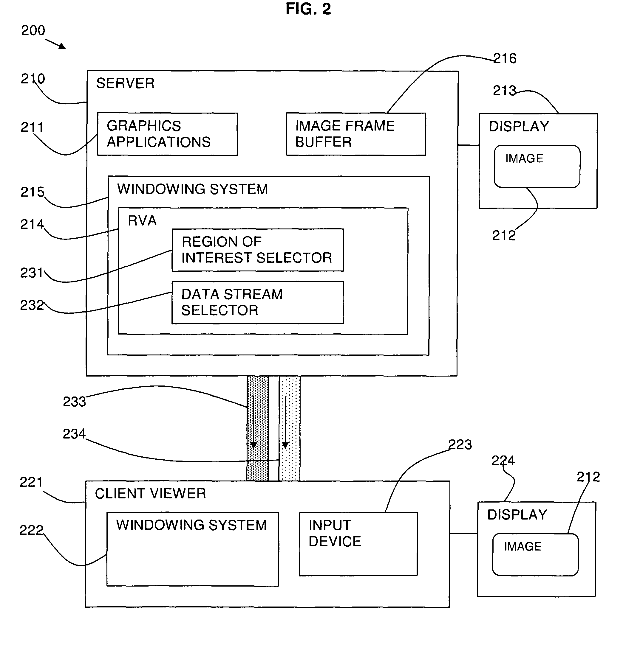
[0026]A remote visualization adapter (RVA) software module 114 is installed on a windowing system 115 of the server sy...


PUM


Abstract

A method and system for optimizing bandwidth usage in remote visualization are provided. The method may comprise determining a region of interest and a region of non-interest of the image; sending data relating to the region of interest via a reliable priority data stream; and sending data relating to the region of non-interest via a less reliable non-priority data stream. The priority data stream may be a high quality and / or high speed data stream, while the non-priority data stream may be a lower quality and / or lower speed data stream. The region of interest and the region of non-interest may be determined in various ways, including via automatic selection (e.g., through the use of image-based algorithms), via an application programming interface of one of a plurality of graphics applications that generate the image, or via manual selection by a user.

Description

RELATED APPLICATION[0001]This application claims priority under 35 U.S.C. §119 to European Patent Application No. 08150253.6 filed Jan. 15, 2008, the entire text of which is specifically incorporated by reference herein.FIELD OF THE INVENTION[0002]The various embodiments described herein relate to the field of remote visualization. In particular, the various embodiments relate to optimizing bandwidth usage in remote visualization.BACKGROUND OF THE INVENTION[0003]Remote visualization solutions allow end-users of a graphical desktop to interact with graphical applications from a remote machine (e.g., a thin client).[0004]Thin client viewers receive images over the network, which are rendered to give end-users the impression that they are using an application locally on their computer or workstation.[0005]There are a number of remote visualization applications available at present. Some of them, such as the exported display feature of X11, Citrix Presentation Server (Citrix is a trade ...

Claims


Application Information

Patent Timeline
Patent Type & Authority Patents(United States)
IPC IPC(8): G06F15/16
CPCG06F3/1431G06F3/1438G06F3/1454H04L67/06H04L67/36H04L67/306H04L69/14G09G2310/04G09G2360/18G09G2370/10H04L67/75
Inventor PASETTO, DAVIDEBOHAN, RONANLEVINS, MARK
Owner LENOVO GLOBAL TECH INT LTD
Learn More