
Coding device and editing device

a technology of coding device and editing device, which is applied in the field of coding, can solve problems such as the complexity of the process, and achieve the effects of reducing the load on the cpu, eliminating unnecessary data rewriting operations, and ensuring compatibility

Active Publication Date: 2013-12-10
PANASONIC INTELLECTUAL PROPERTY MANAGEMENT CO LTD
View PDF18 Cites 0 Cited by
  • Summary
  • Abstract
  • Description
  • Claims
  • Application Information

AI Technical Summary

Benefits of technology

[0017]The present invention is directed to solve the above problems, and has an purpose to provide a coding device capable of eliminating unnecessarily rewriting data when connecting byte streams conforming to the H.264 standard, for example, and an editing device capable of suppressing the CPU processing load and the number of times of rewriting the recording medium, when connecting the byte streams.
[0020]The coding device of the invention substantially eliminates unnecessary data rewriting operations when connecting streams (such as H.264 standard byte streams) containing variable length coded parameters because even if a parameter is changed the code length of the parameter is not changed.
[0021]Further according to the invention, if a header containing a variable length coded parameter must be rewritten when connecting streams, and compatibility can be assured by using code words having the same code length as the original header that is rewritten, the editing device of the invention replaces the code word in the header where the streams are connected with a code word of the same length. On the contrary, if a code word of the same code length is not available, the editing device rewrites the header so that the data length of a specific data unit does not change. The invention thus affords a coding device that does not cause rewriting more data than necessary as a result of rewriting the header, reduces the load on the CPU when editing and connecting streams, and reduces the number of recording medium write operations.

Problems solved by technology

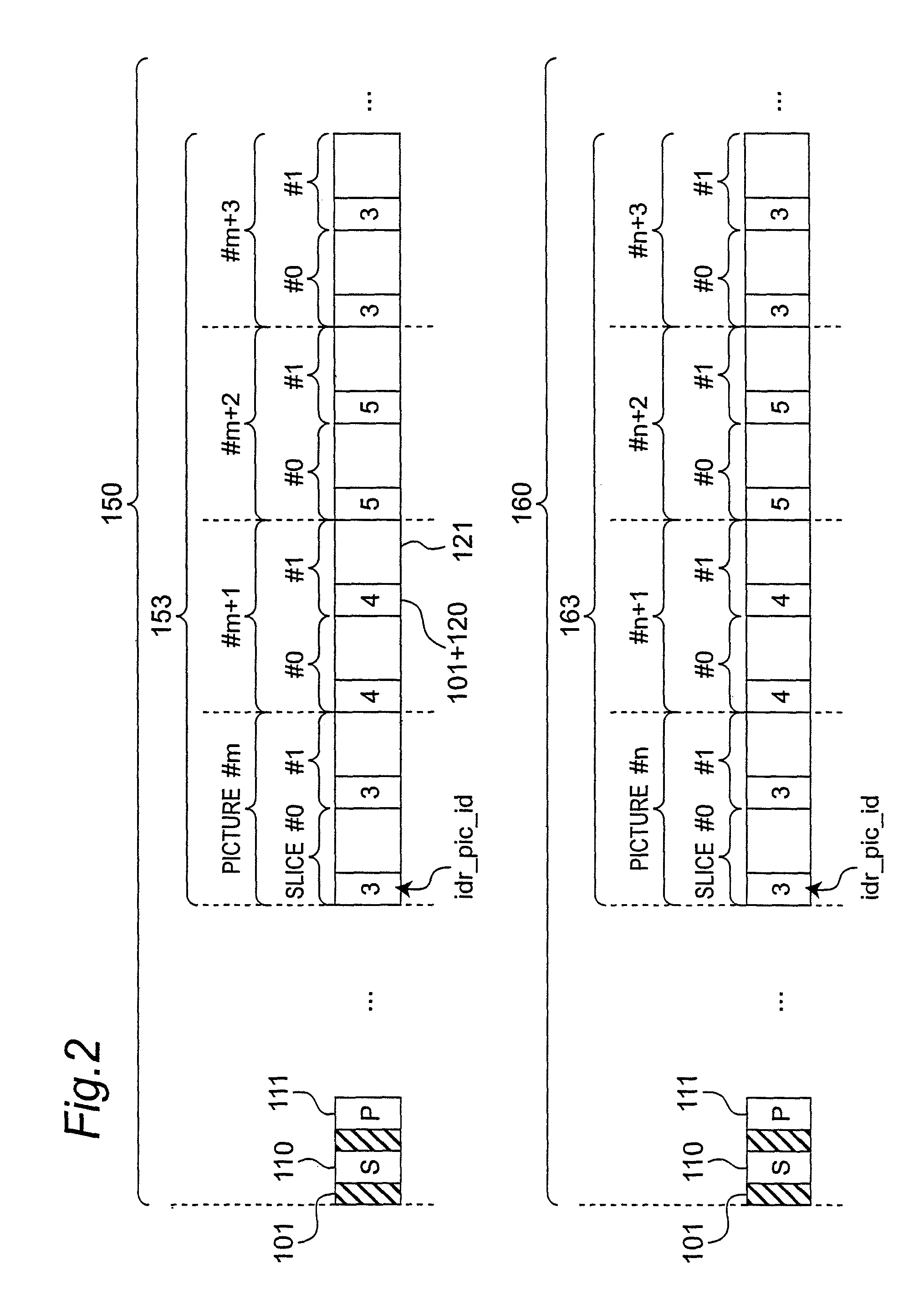
This may make it necessary to modify the data following the idr_pic_id, and the process becomes increasingly complicated.

Method used


Image

  • Coding device and editing device
  • Coding device and editing device
  • Coding device and editing device

Examples


embodiment 1

1. Configuration of Video Coding Device

[0055]The present embodiment describes below a video coding device that controls byte stream coding when connecting a plurality of byte streams which are encoded using IDR (Instantaneous Decoding Refresh) pictures so that necessity to rewrite the idr_pic_id which is the IDR picture identifier (ID) with a code word of a different code length does not occur.

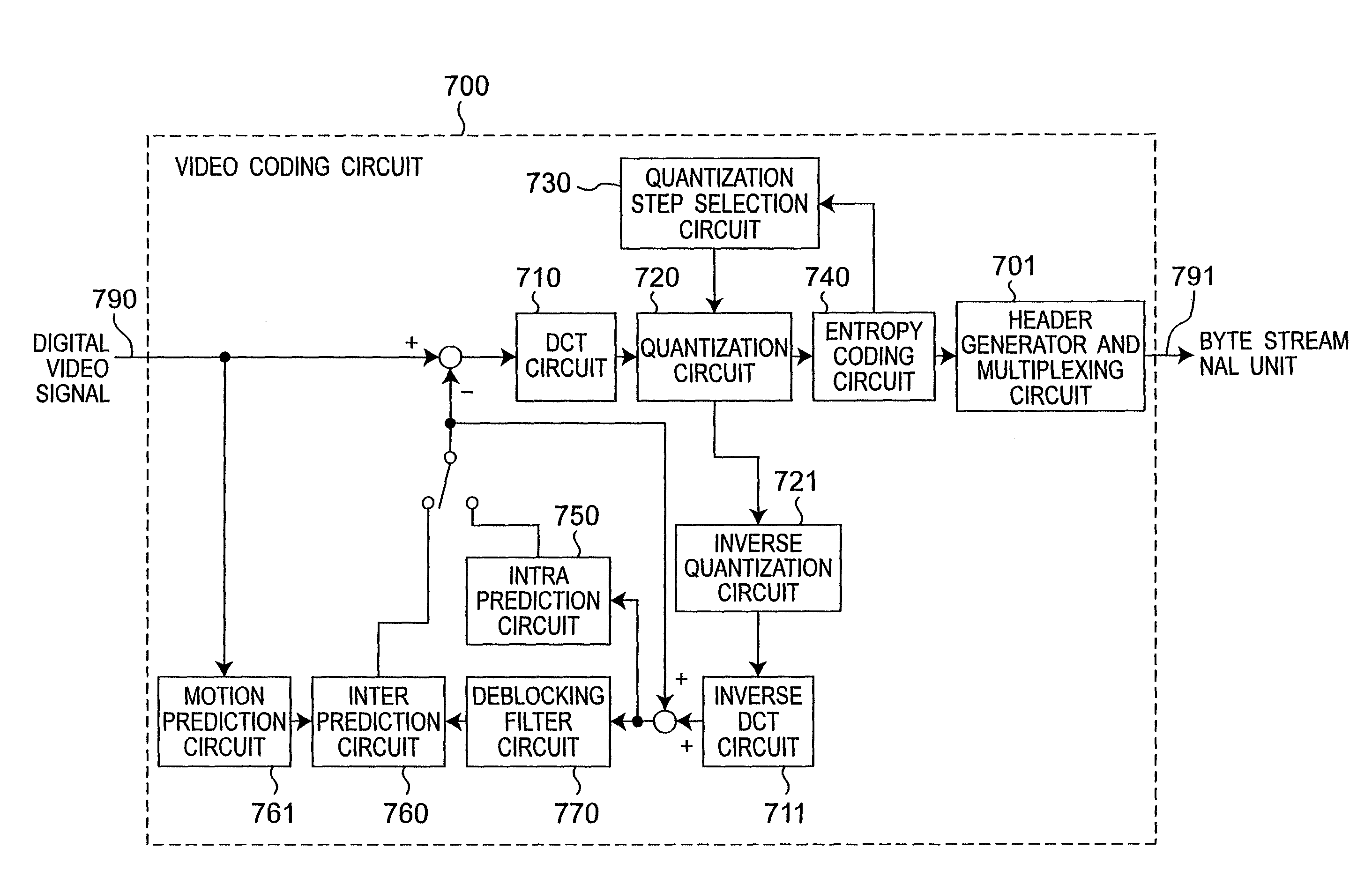
[0056]FIG. 1 shows the video coding circuit included in the video coding device according to this embodiment of the invention. This video coding circuit 700 includes a header generator and multiplexing circuit 701, a DCT circuit 710, an inverse DCT circuit 711, a quantization circuit 720, an inverse quantization circuit 721, a quantization step selection circuit 730, an entropy coding circuit 740, a intra prediction circuit 750, a inter prediction circuit 760, a motion prediction circuit 761, and a deblocking filter circuit 770. The motion prediction circuit 761 and the inter prediction circui...

embodiment 2

[0080]The present embodiment describes below a video coding device that connects and encodes plural byte streams without necessity to rewrite the pic_parameter_set_id that is identifier of the PPS (picture parameter set). This embodiment is particularly useful when connecting a plurality of byte streams in which plural PPS are coded. The basic configuration of the video coding device is the same as in the first embodiment of the invention described above.

[0081]In this embodiment of the invention the header generator and multiplexing circuit 701 stores and manages the combinations of PPS content and pic_parameter_set_id (“PPSID”) values. More specifically, if the syntax is different for all encoded PPS in the streams generated by the video coding device according to this embodiment of the invention, the coding process assigns a different PPSID to each PPS.

[0082]FIG. 6 is a table for storing and managing the PPS in the header generator and multiplexing circuit 701. When the PPS syntax...

embodiment 3

[0087]This embodiment of the invention describes a video editing device that can encode the IDR pictures without duplicating the idr_pic_id of the pictures at the seam and can minimize the area on the recording medium where the values are rewritten when connecting a plurality of byte streams encoded with IDR pictures.

1. Configuration of the Video Editing Device

[0088]FIG. 10 shows a video editing device according to this embodiment of the invention. This video editing device 501 is rendered using a computer 502. The computer 502 has an internal drive 590 or an external drive 591 for accessing the recording medium 500 containing video data. The recording medium 500 is a computer-readable medium such as a memory card, an optical disc, or a removable hard disk drive, for example. The computer 502 could be connected by a network cable 594 or wirelessly to a network for sending and receiving video data. A display 592 and input device 593 such as a mouse and keyboard are also connected to ...


PUM


Abstract

A coding device includes a coding unit (740) for encoding an input digital signal using code words contained in one of a plurality of variable length code word groups, and a multiplexer (701) for generating a stream by generating a parameter (such as idr_pic_id) describing specific information about the stream, encoding the parameters, and adding it to the output data from the coding unit. The length of the code words contained in any single variable length code word group is the same. The multiplexer selects one variable length code word group containing three or more code words out of the plural groups, and codes the parameter using one code word selected from the code words contained in the selected group.

Description

TECHNICAL FIELD[0001]The present invention relates to a coding device for encoding using a coding method that embeds information by variable length coding, and to an editing device for editing a stream generated by the coding device.BACKGROUND ART[0002]Variable length coding (VLC) is a fundamental technology used in encoding source data, and compresses the data by allocating code words of different lengths according to the likelihood of a particular data source symbol. Using coding rules such as shown in FIG. 24, for example, values (codeNum) greater than 0 are converted to variable length code words of 1, 3, 5, . . . bits. Note that the bit string part denoted xn, xn-1, . . . x0 is the part of the bit string that varies according to the data value (codeNum). For example, a value (codeNum) of 1 or 2 is encoded to a 3 bit code word, and values from 7 to 14 are converted to a 7 bit code word. The length of the code words after encoding thus varies according to the data value (codeNum)...

Claims


Application Information

Patent Timeline
Patent Type & Authority Patents(United States)
IPC IPC(8): H04N7/12H04N19/00H04N5/91H04N19/152H04N19/423H04N19/46H04N19/48H04N19/503H04N19/593H04N19/61H04N19/625H04N19/70H04N19/82H04N19/91
CPCG11B27/034G11B27/3027H04N21/23424H04N21/44016H04N19/70H04N19/61H04N19/91G11B27/031G11B2220/20
Inventor TANAKA, TOSHIHIROSAITO, HIROSHI
Owner PANASONIC INTELLECTUAL PROPERTY MANAGEMENT CO LTD
Learn More