Method for starting up DC-DC converter

a dc-dc converter and converter technology, applied in the direction of dc-dc conversion, power conversion systems, instruments, etc., can solve the problems of reducing the reliability of the apparatus, increasing the loss, and breaking the mosfet constituting the switching device, so as to improve the reliability of the converter, minimize or avoid malfunction, and prevent the effect of the switching devi

Inactive Publication Date: 2013-12-10
FUJI ELECTRIC CO LTD
View PDF9 Cites 1 Cited by
  • Summary
  • Abstract
  • Description
  • Claims
  • Application Information

AI Technical Summary

Benefits of technology

[0023]In consideration of the aforementioned problems, an object of embodiments of the invention is to provide a method for starting up a DC-DC converter, by which an output voltage can be prevented from overshooting and body diodes of switching devices can be prevented from reverse recovery.
[0024]It is another object of embodiments of the invention to provide a method for starting up a DC-DC converter, by which switching devices can be prevented from malfunction caused by induced noise when the DC-DC converter is started up.
[0025]Embodiments of the invention provide a method for starting up a DC-DC converter so as to obtain a DC output, the DC-DC converter including a full bridge formed by a first series circuit and a second series circuit connected in parallel to a DC power supply, the first series circuit including a first switching device and a second switching device connected in series, the second series circuit including a third switching device and a fourth switching device connected in series, an internal connection point of the first series circuit being connected to one end of a primary side of a transformer, an internal connection point of the second series circuit being connected to the other end of the primary side of the transformer, a rectification device being connected to a secondary side of the transformer, the starting-up method including the steps of: turning on the first switching device with a first driving signal whose duty ratio is lower than 50%, turning on the second switching device with a second driving signal whose duty ratio is lower than 50% in a period when the first switching device is OFF, and driving the third switching device and the fourth switching device respectively with third and fourth driving signals whose duty ratios are lower than 50% and whose phases are shifted from the first and second driving signals of the first switching device and the second switching device; and increasing a shift quantity of the phases to increase an output voltage value of the DC output gradually.
[0026]According to embodiments of the invention, it is possible to start up the DC-DC converter while minimizing, or without causing, overshooting of the output voltage and without bringing reverse recovery into any body diode of the switching devices.
[0027]In addition, it is possible to clamp a driving voltage with a reverse bias when the switching devices are OFF at the starting-up time of the DC-DC converter. It is therefore possible to minimize or avoid malfunction due to the switching devices which are turned on by induced noise generated from the inside of the apparatus or another apparatus, etc. Thus, the DC-DC converter can be started up safely so that the reliability of the converter can be improved.
[0028]In addition, voltages applied to components at the starting-up time of the DC-DC converter can be reduced. Thus, low-withstanding voltage and low-loss components can be used to make the apparatus lower in loss and lower in cost.

Problems solved by technology

Typically, when the voltage-time change rate dv / dt at the reverse recovery of the body diode is beyond its maximum rated value, there is a fear that a MOSFET constituting the switching device is broken.
Thus, occurrence of the reverse recovery increases loss and lowers the reliability of the apparatus remarkably.
However, to stabilize a forward bias voltage and a reverse bias voltage even if the duty ratio of an input voltage to a transformer is not about 50%, by use of a gate drive circuit which is possible to apply a reverse bias voltage between a gate and a source, the reverse bias voltage cannot be obtained if the pulse width in each gate signal is not wide enough.
Thus, the capacitor cannot provide a sufficient reverse bias voltage Vr.
As a result, there is a fear that the switching devices 1 to 4 can be turned on due to induced noise from the outside, or the like, to thereby result in reduction of the reliability of the converter.
When the DC-DC converter is started up by gate signals each having a pulse width expanded in advance as shown in FIG. 13 in order to avoid the fear of switching devices 1 to 4 being turned on by induced noise, there is, however, another fear that the output voltage Vo may surpass the withstanding voltage of an apparatus connected thereto and therefore the apparatus may be broken.
As a result, secondary-side components of the DC-DC converter or an apparatus connected to the load may be broken.
In order to avoid this problem of high output voltages harming components, high-voltage components are typically used in the secondary-side components and the apparatus connected to the load, thereby causing increase in cost and loss.

Method used


Image

  • Method for starting up DC-DC converter
  • Method for starting up DC-DC converter
  • Method for starting up DC-DC converter

Examples


first embodiment

[0044]a method for starting up a DC-DC converter will be described.

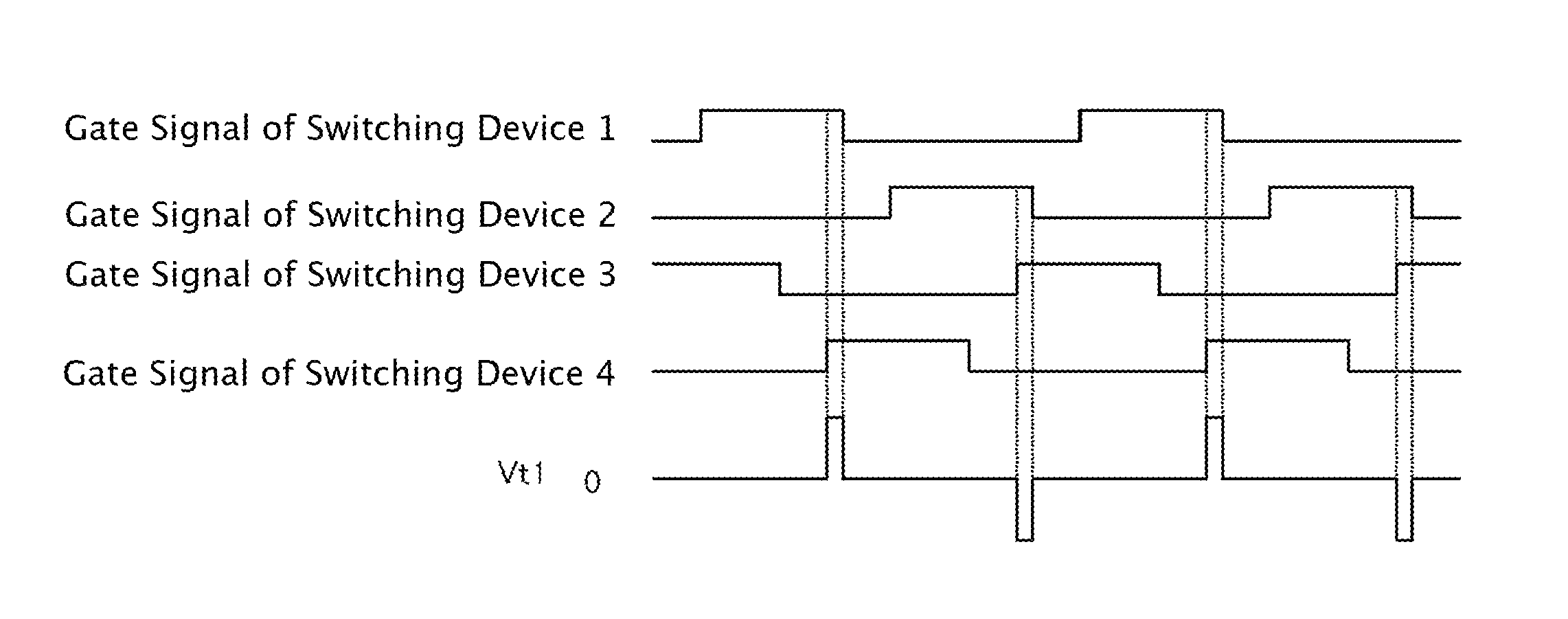
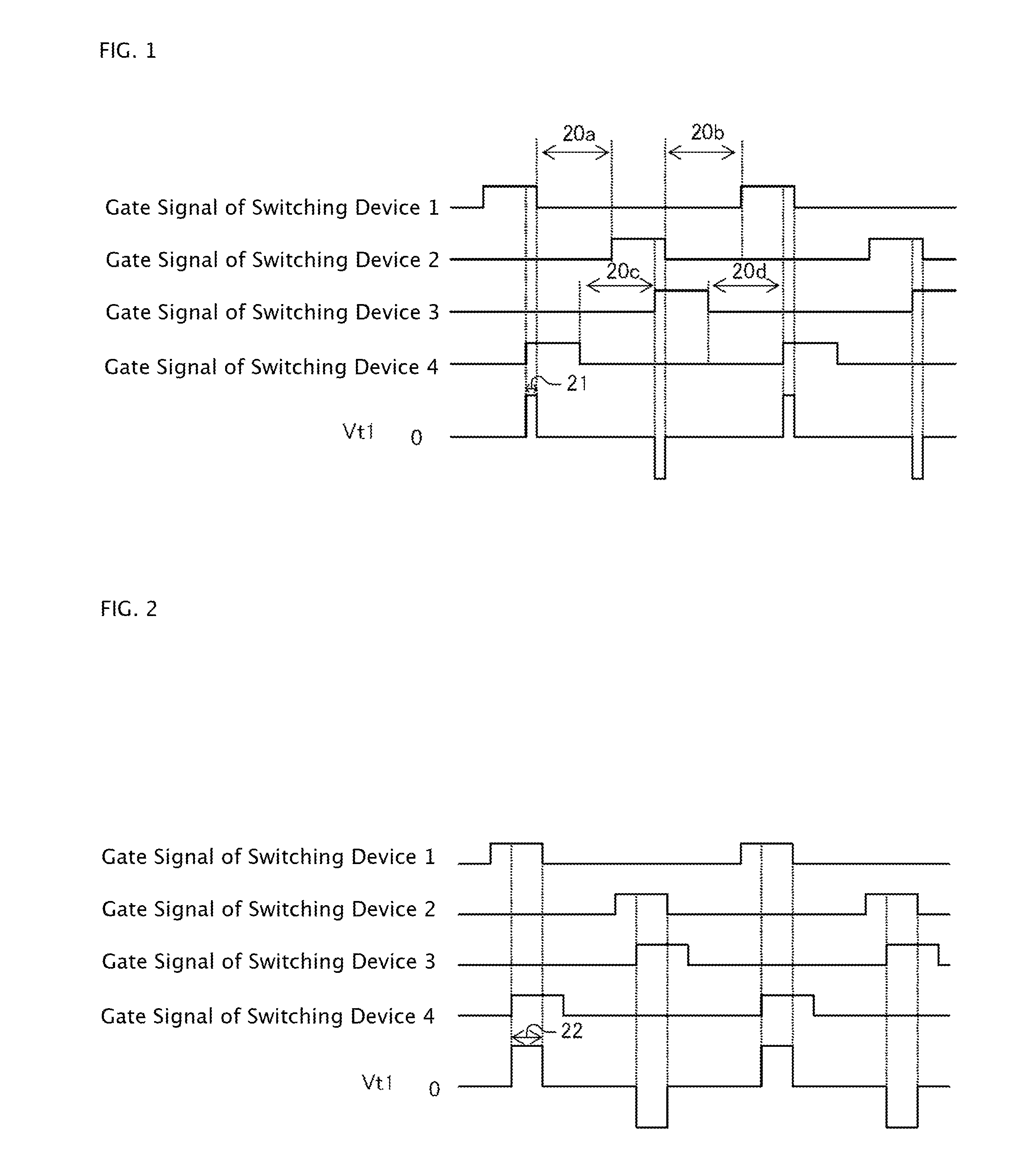
[0045]FIG. 1 is a chart for explaining the first embodiment of the method for starting up the DC-DC converter. FIG. 1 shows changes of gate signals applied to switching devices forming a bridge on a primary side of a transformer and a voltage value Vt1 on the primary side of the transformer when the DC-DC converter is started up.

[0046]First to fourth gate signals are applied to gates of switching devices 1 to 4 to switch on / off the switching devices respectively. Each of the switching devices 1 to 4 is turned ON when a gate signal applied thereto is H, and OFF when the gate signal is L.

[0047]The gate signal of the switching device 2 is turned on in the period when the gate signal of the switching device 1 is OFF. The gate signal of the switching device 4 is turned on in the period when the gate signal of the switching device 3 is OFF. Here is shown an example in which all the gate signals have equal pulse widths. How...

second embodiment

[0056]Next, a starting-up method will be described.

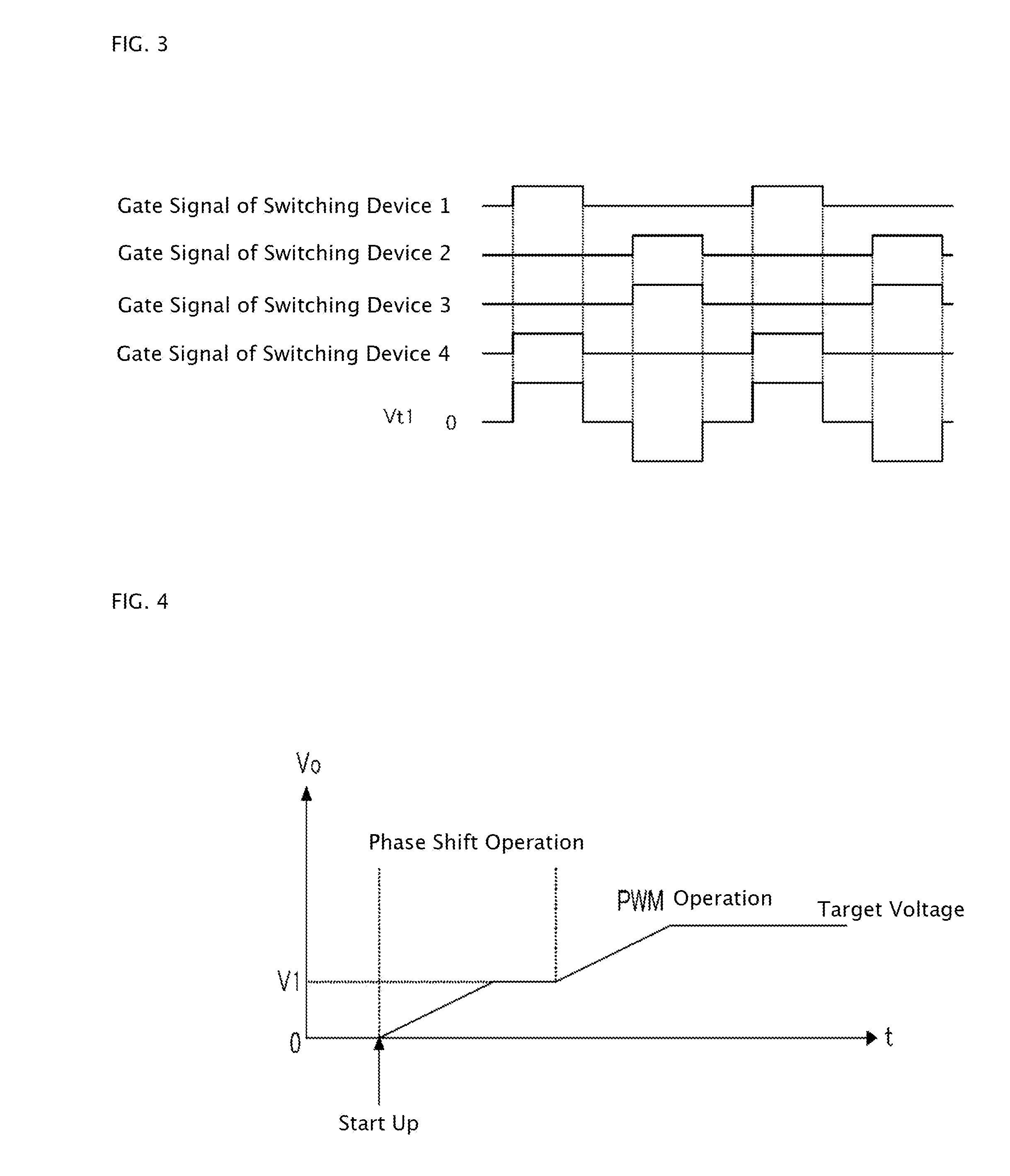
[0057]In the starting-up method according to the first embodiment, the phase of each gate signal of the switching devices 3 and 4 is shifted gradually as described above. Accordingly, when the phase has been shifted to make the phase of each gate signal of the switching devices 1 and 4 coincide with the phase of each gate signal of the switching devices 2 and 3, the output voltage Vo cannot be increased further. The starting-up method according to the second embodiment is to cope with this case.

[0058]According to the second embodiment, the phase of each gate signal of the switching devices 3 and 4 is shifted relatively to the phase of each gate signal of the switching devices 1 and 2 in the same manner as in the first embodiment, so as to increase the value of the voltage Vt1 gradually. As soon as the voltage Vt1 reaches a specific value, the phase shift operation is switched to PWM operation.

[0059]FIG. 3 is a chart showing each ga...

third embodiment

[0063]Next, a starting-up method will be described.

[0064]First, according to the third embodiment, the phases of the switching devices 3 and 4 are gradually shifted relative to the phases of the switching devices 1 and 2 so as to increase the output voltage Vo gradually in the same manner as in the first embodiment.

[0065]Description will be made on the pulse width of each gate signal at this time. The DC-DC converter is started up with each driving signal whose pulse width is large enough to increase the output voltage Vo to the target voltage or higher in the phase shift operation as shown in FIG. 5. The phases of the gate signals of the switching devices 3 and 4 are shifted relatively to the phases of the gate signals of the switching devices 1 and 2 in the same manner as in the first embodiment. Thus, the pulse width of the voltage Vt1 on the primary side of the transformer 9 is increased gradually to increase the output voltage Vo as shown in FIG. 6. However, the pulse width of...


PUM


Abstract

Aspects of the invention provide a method for starting up a DC-DC converter by which an output voltage can be prevented from overshooting and body diodes of switching devices can be prevented from reverse recovery. In the start-up method, the phases of gate signals of third and fourth switching devices are gradually shifted relative to the phases of gate signals of first and second switching devices. With increase of the phase shift, a voltage on a primary side of a transformer is also increased, and an output voltage is also increased.

Description

BACKGROUND OF THE INVENTION[0001]1. Field of the Invention[0002]The present invention relates to a method for stating up an insulated DC-DC converter which has a full-bridge configuration on a primary side of a transformer.[0003]2. Description of Related Art[0004]FIG. 9 shows an example of a DC-DC converter disclosed in Japanese Patent Application No. 2009-18302.[0005]The DC-DC converter in FIG. 9 has a full-bridge configuration on a primary side of a transformer 9. MOSFETs are used as switching devices 1 to 4 which form a primary-side bridge. On the other hand, rectification devices 7 and 8 are used on a secondary side of the transformer 9. Capacitors 13 to 16 are parasitic capacitances of the switching devices 1 to 4 respectively, and capacitors 17 and 18 are parasitic capacitances of the rectification devices 7 and 8.[0006]In FIG. 9, the portion of a gate drive circuit for generating gate signals is not shown. The gate signals serve as driving signals for switching on / off the swi...

Claims


Application Information

Patent Timeline
Patent Type & Authority Patents(United States)
IPC IPC(8): H02M3/335
CPCH02M1/36
Inventor MINO, KAZUAKI
Owner FUJI ELECTRIC CO LTD
Why Eureka
Try Eureka