Operating noise control device and operating noise control method for vehicle
a technology of operating noise and control device, which is applied in the direction of electric devices, process and machine control, instruments, etc., can solve the problem that the driver may not want sustained quiet operation, and achieve the effect of improving the noise of operation
- Summary
- Abstract
- Description
- Claims
- Application Information
AI Technical Summary
Benefits of technology
Problems solved by technology
Method used
Image
Examples
first embodiment
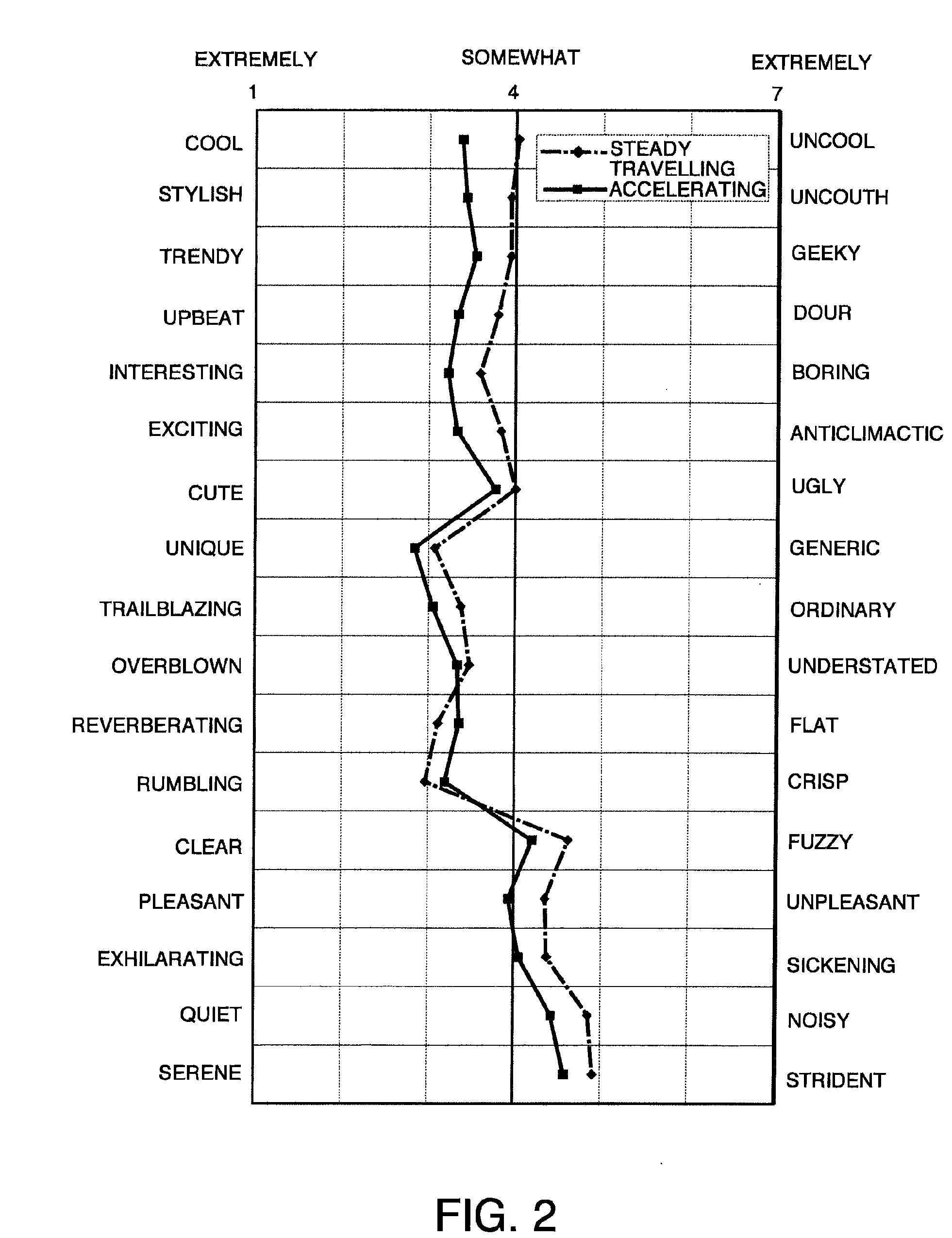
[0040]Referring to FIGS. 1 and 2, FIGS. 3A and 3B, FIGS. 4A-4C, FIG. 5, FIGS. 6A and 6B, FIGS. 7A and 7B, FIGS. 8A and 8B and FIG. 9 of the drawings, this invention will be described.
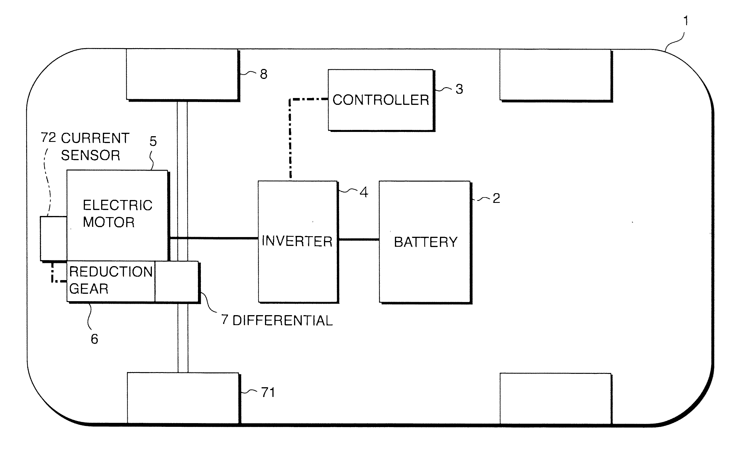
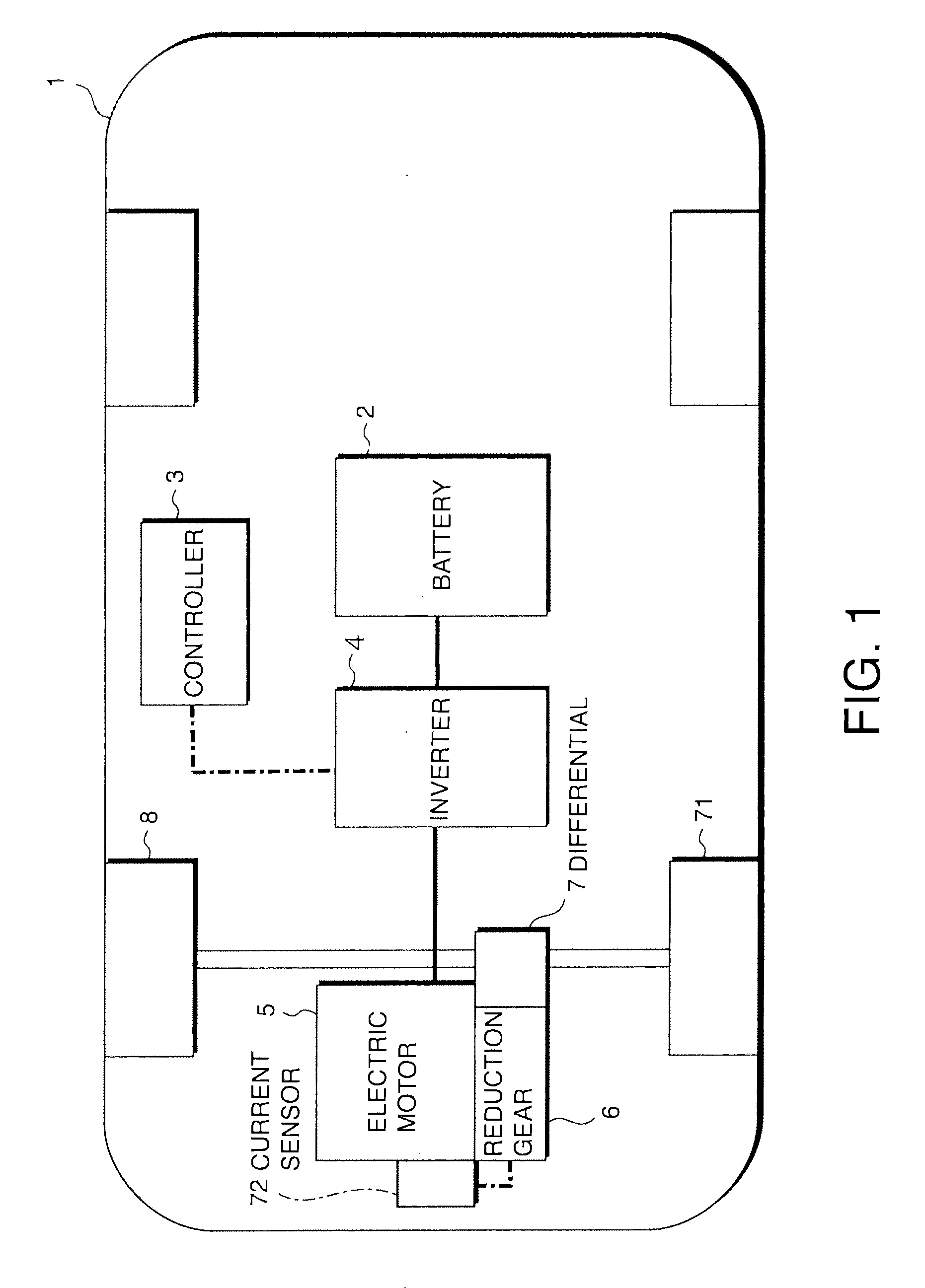
[0041]Referring to FIG. 1, a vehicle 1 equipped with an operating noise control device according to this invention travels as drive wheels are rotationally driven by an electric motor 5 with electric power supplied from a battery 2. Power is stored in the battery 2 in advance by supplying electric power from an external source.
[0042]DC power supplied from the battery 2 is first converted to three-phase AC power at an inverter 4 and thus is input as three-phase AC power to the electric motor 5. The electric motor 5 is constituted with a synchronous AC motor. The rotation of the electric motor 5 is transmitted to drive wheels 71 via a reduction gear 6 and a differential 7. The inverter 4 converts the electrical current based upon a command signal issued by a controller 3.
[0043]The controller 3 calculates ...
second embodiment
[0074]Referring to FIGS. 10A-10C, FIGS. 11A and 11B, FIGS. 12A-12C, FIGS. 13A-13C, FIGS. 14A and 14B and FIGS. 15A and 15B, this invention will be described.
[0075]This embodiment assumes a hardware configuration identical to that of the first embodiment and is distinguishable from the first embodiment only in the method adopted for higher-order component current application.
[0076]FIGS. 10A-10C indicate that the controller 3 in this embodiment controls the drive current for the electric motor 5 with current instruction values in FIG. 10C calculated by multiplying the basic current in FIG. 10A by a correction coefficient Kn shown in FIG. 10B and defined in expression (4) below. A drive current corresponding to the current instruction values is then applied to the coils at the electric motor 5.
Kn=1+q·sin {(6+p)·θ+θn} (4)
[0077]where,[0078]θn=2π·(6+p)+θn-1;[0079]θ=electrical angle; and[0080]p, q,=coefficients determined in correspondence to the vehicle operating condition.
[0081]As expre...
third embodiment
[0092]Referring to FIG. 16, this invention will be described.
[0093]This embodiment is achieved by further adding an external operation panel 13 via which the driver is able to select any beat noise setting to the beat noise generation system in the second embodiment.
[0094]The external operation panel 13 is installed near the driver's seat in the vehicle 1. The external operation panel 13 includes a beat noise ON / OFF switch 14, a beat frequency adjustment dial 15, and a beat strength adjustment dial 16.
[0095]The beat ON / OFF switch 14 can be set to one of three positions, OFF, AUTO and MANUAL. The beat frequency adjustment dial 15 is operated when setting the coefficient p in Equation (4). The beat strength adjustment dial 16 is operated when setting the coefficient q in Equation (4).
[0096]If the driver selects the OFF position at the beat ON / OFF switch 14, the controller 3 does not add the higher-order component current to the drive current and thus, no beat noise is generated.
[0097]...
PUM
 Abstract
Description
Claims
Application Information
 - R&D
- Intellectual Property
- Life Sciences
- Materials
- Tech Scout
- Unparalleled Data Quality
- Higher Quality Content
- 60% Fewer Hallucinations
Browse by: Latest US Patents, China's latest patents, Technical Efficacy Thesaurus, Application Domain, Technology Topic, Popular Technical Reports.
© 2025 PatSnap. All rights reserved.Legal|Privacy policy|Modern Slavery Act Transparency Statement|Sitemap|About US| Contact US: help@patsnap.com


