
Method and apparatus for amplifying a radio frequency signal

a radio frequency signal and amplifier technology, applied in the direction of amplifiers, amplifiers with semiconductor devices only, amplifiers with semiconductor devices, etc., can solve the problems of inability to achieve the desired characteristics of good linearity, high efficiency, and high power operation over a wide bandwidth, and achieve the desired characteristics easily in the same amplifier. , the effect of inefficiency at all output power levels

Active Publication Date: 2013-11-26
MOTOROLA SOLUTIONS INC
View PDF13 Cites 62 Cited by
  • Summary
  • Abstract
  • Description
  • Claims
  • Application Information

AI Technical Summary

Benefits of technology

The present invention relates to a new design for a high power radio frequency amplifier used in wireless communication systems. The invention aims to optimize the amplifier's performance by balancing conflicting requirements of linearity and efficiency, while also addressing the limitations of prior art Doherty amplifiers. The new design addresses issues such as fixed frequency limiting quarter-wave transmission structures, adherence to classical Doherty non-inverting topology, use of a larger number of hybrid combiner based phase shifting elements, and failure to use power amplifying devices with minimal output capacitance. The invention provides a solution for multi-band operation and improves the bandwidth coverage of the amplifier.

Problems solved by technology

That is, the characteristics of good linearity, high efficiency, and high power operation over a wide bandwidth, while desired, cannot easily be achieved simultaneously in the same amplifier.
For example, Class A amplifiers can be very linear and have wideband performance but are inefficient at all output power levels and may be completely impractical at high power levels for reasons of power consumption and heat generation.
Class AB amplifiers have decent linearity and high power operation with moderate bandwidths but poor efficiency, whereas amplifiers operating as class C or D have poor linearity but high efficiency.
For these reasons, high power Doherty amplifiers of the prior art are tailored mostly to single band operation only and are not suitable for multi-band operation.

Method used


Image

  • Method and apparatus for amplifying a radio frequency signal
  • Method and apparatus for amplifying a radio frequency signal
  • Method and apparatus for amplifying a radio frequency signal

Examples


Embodiment Construction

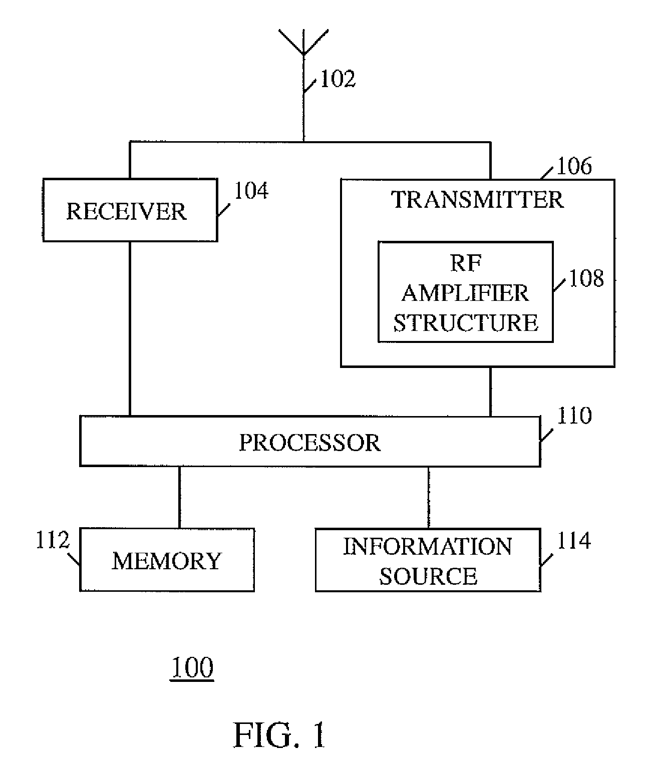
[0022]To address the need for a high power Doherty amplifier that is suitable for multi-band operation, a radio frequency (RF) amplifier structure is provided that provides highly efficient RF signal amplification across a wide bandwidth, when implemented in both inverting and non-inverting Doherty designs. In a first embodiment of the present invention using an inverting topology realized by employing matching impedance transform circuits that comprise a low pass multiple section inductance-capacitance circuit and that provides impedance matching between the output of an amplifier device and a power combiner, wherein the output matching impedance transform circuit has approximately an odd multiple of 90 electrical degrees over the RF amplifier structure's frequency range of operation, and adjustable phase delay circuits that route an amplified RF signal to the power combiner and that are controllably adjusted based on a frequency of an RF input signal.

[0023]Generally, the first emb...


PUM


Abstract

A radio frequency (RF) amplifier structure provides highly efficient RF signal amplification across a wide bandwidth, when implemented in both inverting and non-inverting Doherty designs, by employing matching impedance transform circuits that comprise a low pass multiple section inductance-capacitance circuit and that provides impedance matching between the output of an amplifier device and a power combiner, wherein the output matching impedance transform circuit has approximately an odd multiple of 90 electrical degrees over the RF amplifier structure's frequency range of operation, and adjustable phase delay circuits that route an amplified RF signal to the power combiner and that are controllably adjusted based on a frequency of an RF input signal over an operating frequency range of the RF amplifier structure.

Description

CROSS-REFERENCE TO RELATED APPLICATION[0001]This application claims priority from U.S. provisional application Ser. No. 61 / 695,687, entitled “METHOD AND APPARATUS FOR AMPLIFYING A RADIO FREQUENCY SIGNAL,” filed Aug. 31, 2012, which is application is commonly owned and incorporated herein by reference in its entirety.FIELD OF THE INVENTION[0002]The present invention relates generally to wireless communication systems, and in particular to the structure of a radio frequency amplifier in a wireless communication system.BACKGROUND OF THE INVENTION[0003]Radio frequency amplifiers designed for modern wireless communication system formats such as Code Division Multiple Access (CDMA), Universal Mobile Telecommunications System (UMTS), Orthogonal Frequency-division Multiple Access (OFDMA), Long Term Evolution (LTE), and multi-carrier systems that have significant signal peak-to-average requirements, need to balance conflicting performance characteristics such as linearity, efficiency, high s...

Claims


Application Information

Patent Timeline
Patent Type & Authority Patents(United States)
IPC IPC(8): H03F3/68
CPCH03F1/0288H03F3/195H03F3/24H03F2200/192
Inventor ROOT, LOREN F.
Owner MOTOROLA SOLUTIONS INC
Learn More