
Gas-insulated vacuum circuit breaker

a vacuum circuit breaker and vacuum circuit technology, applied in the direction of air-break switch, high-tension/heavy-dress switch, switchgear arrangement, etc., can solve the problems of shortening the mechanical life of the vacuum valve, increasing the cost of the vacuum valve, and reducing the pressure of the bellows, so as to prolong the mechanical life of the bellows and reduce the pressure. , the effect of the bellows

Active Publication Date: 2013-11-26
HITACHI LTD
View PDF11 Cites 9 Cited by
  • Summary
  • Abstract
  • Description
  • Claims
  • Application Information

AI Technical Summary

Benefits of technology

The gas-insulated vacuum circuit breaker allows for monitoring and controlling of the pressure inside the circuit breaker. This helps to maintain a safe and stable pressure level, reducing the pressure on the bellows and improving the mechanical life of the breaker. The design also allows for a smaller size of the movable conductor shaft, making it more practical for use in smaller circuit breakers.

Problems solved by technology

This produces difference in pressure between the outside and the inside of the bellows, possibly resulting in shortening the mechanical life of that bellows.
However, use of a paired bellows in the conventional gas insulated vacuum circuit breaker causes a vacuum valve to be expensive.
In this construction, there is a risk of a small leakage occurring intermittently or continuously over a long period of time through the gastight holding part attributable to the switching movements of the vacuum circuit breaker.
With this case, the internal pressure of the intermediate room gradually rises and reaches an abnormal pressure value inviting a risk of an increased pressure difference between the inside and the outside of the bellows.

Method used


Image

  • Gas-insulated vacuum circuit breaker
  • Gas-insulated vacuum circuit breaker
  • Gas-insulated vacuum circuit breaker

Examples


embodiment 1

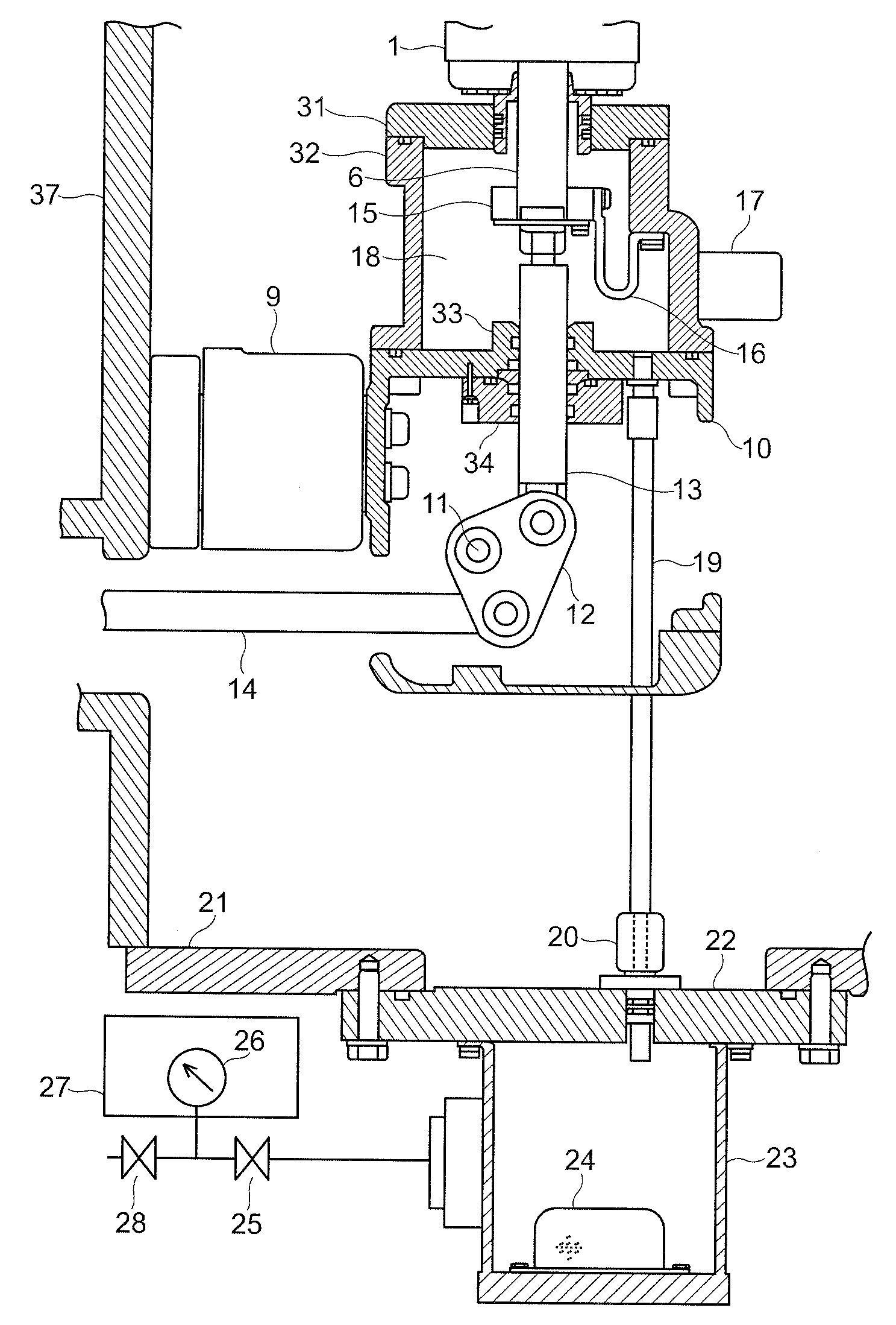
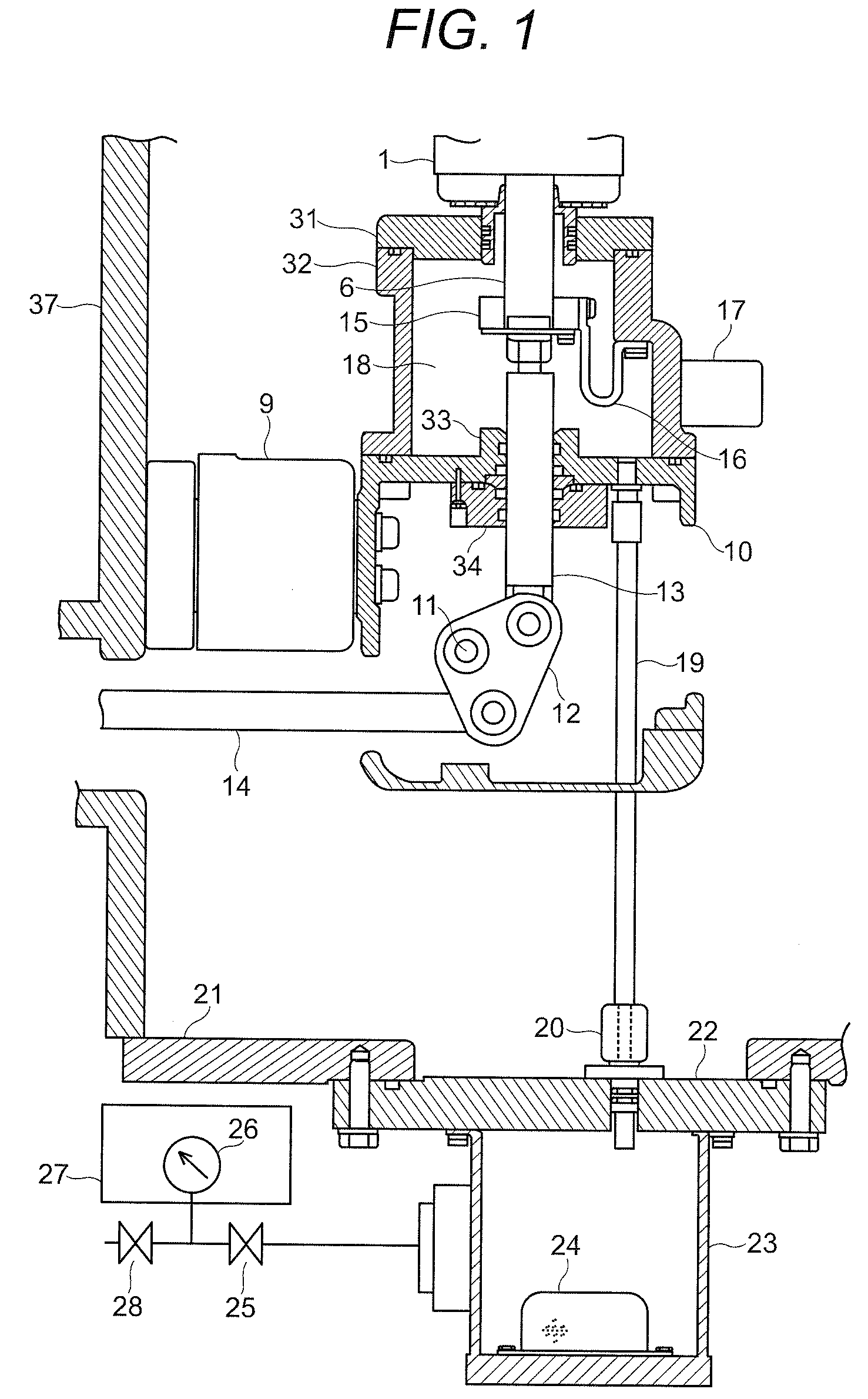
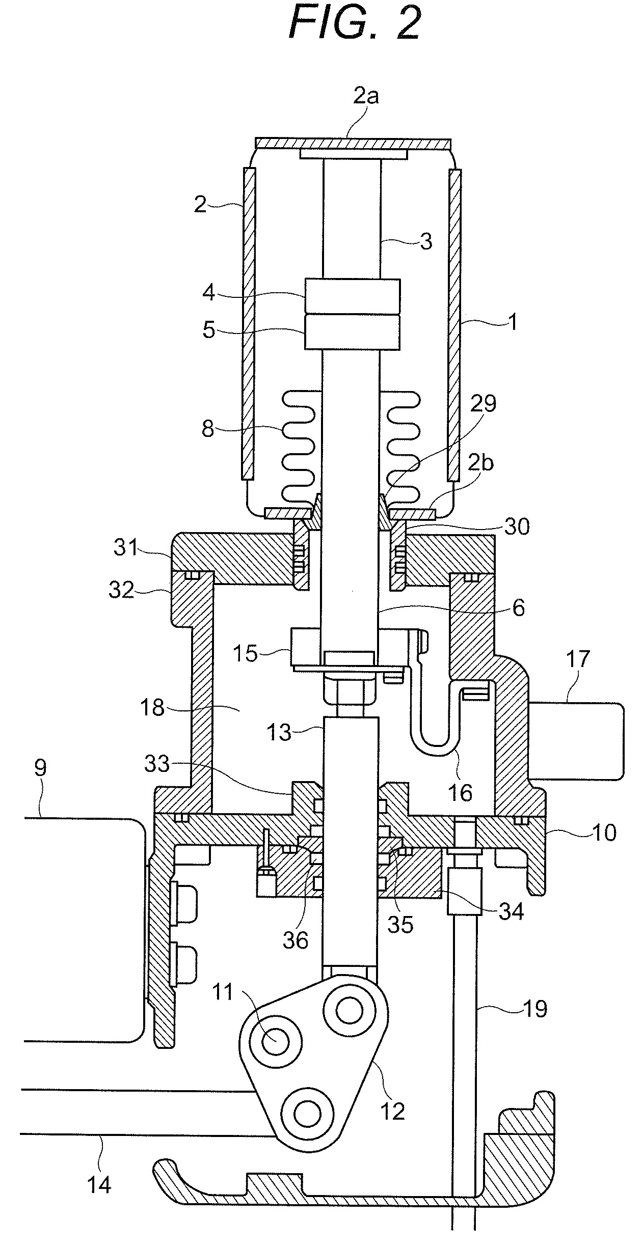
[0016]The following explains an embodiment, which is illustrated in FIGS. 1 and 2, of a gas-insulated vacuum circuit breaker by the present invention.

[0017]As FIG. 2 illustrates, a vacuum valve 1 is arranged in a sealed tank (not illustrated) filled with insulating gas compressed to a pressure of several-atmosphere, being insulated electrically from the sealed tank.

[0018]The vacuum valve 1 comprises a vacuum tank 2 the inside of which is kept vacuum. The vacuum valve 1 includes an end flanges 2a and 2b that hermetically seal both of axial ends of the vacuum tank 2, a fixed electrode 4 fixed on the end flange 2a of the vacuum tank 2 via an fixed conductor shaft 3, a movable electrode 5 that is openable from the fixed electrode 4, a movable conductor shaft 6 supporting the movable electrode 5 and being led out of the vacuum tank 2, and a bellows 8 installed between the end flange 2b and the movable conductor shaft 6 so that the vacuum of the vacuum tank 2 will be maintained being prot...


PUM


Abstract

Sealed chamber for monitoring pressure 23 is provided on sealed tank 37. Sealed tank 37 is filled with insulating gas. And, a connection using insulated pipe 19 is provided between medium-pressure space 18 that makes a medium pressure and sealed chamber for monitoring pressure 23. In sealed chamber for monitoring pressure 23, a pressure monitoring and controlling means is provided for monitoring the internal pressure thereof to activate the pressure-release control in response to the situation where the monitored internal pressure has reached the predetermined setting value. The pressure monitoring and controlling means includes solenoid valve 28 that is capable of opening sealed chamber for monitoring pressure 23 to the atmosphere, pressure detector 26 that detects the internal pressure, and pressure monitor 27, which activates solenoid valve 28 for pressure-release when pressure detector 26 detects that the internal pressure has reached the predetermined abnormal pressure value.

Description

TECHNICAL FIELD[0001]The present invention relates to a gas-insulated vacuum circuit breaker including a vacuum valve arranged in a sealed tank that is filled with insulating gas.BACKGROUND ART[0002]It is generally known that electric power stations such as power plants and substations use gas-insulated breakers having a construction such that high-voltage conductors are arranged in a sealed tank filled with insulating gas at a pressure of several-atmosphere and the conductors are electrically insulated from the tank. It is also known that gas-insulated vacuum circuit breakers using vacuum valves are used instead of usual kind of gas-insulated switchgears that are usually used.[0003]The vacuum valve has a pair of openable electrodes accommodated in a vacuum tank kept in a vacuum state and a bellows that prevents the vacuum-leakage of the vacuum tank attributable to the opening movement of the movable electrode while permitting the opening movement of the movable electrode. Because o...

Claims


Application Information

Patent Timeline
Patent Type & Authority Patents(United States)
IPC IPC(8): H01H33/02
CPCH02B13/0354H02B13/0655H01H33/666H01H33/662H01H33/668H02B13/035
Inventor HATANAKA, HAYATOSHIN, TEYONFUJITA, MASAHIKO
Owner HITACHI LTD
Learn More