Eureka AIR delivers breakthrough ideas for toughest innovation challenges, trusted by R&D personnel around the world.

Connector for connecting cable and terminal of same

a technology of connecting cable and terminal, which is applied in the direction of coupling device connection, two-part coupling device, electrical apparatus, etc., can solve the problems of complicated housing shape, and achieve the effect of simple structure, reliable connection and convenient insertion

Active Publication Date: 2013-11-26
MOLEX INC
View PDF23 Cites 2 Cited by
  • Summary
  • Abstract
  • Description
  • Claims
  • Application Information

AI Technical Summary

Benefits of technology

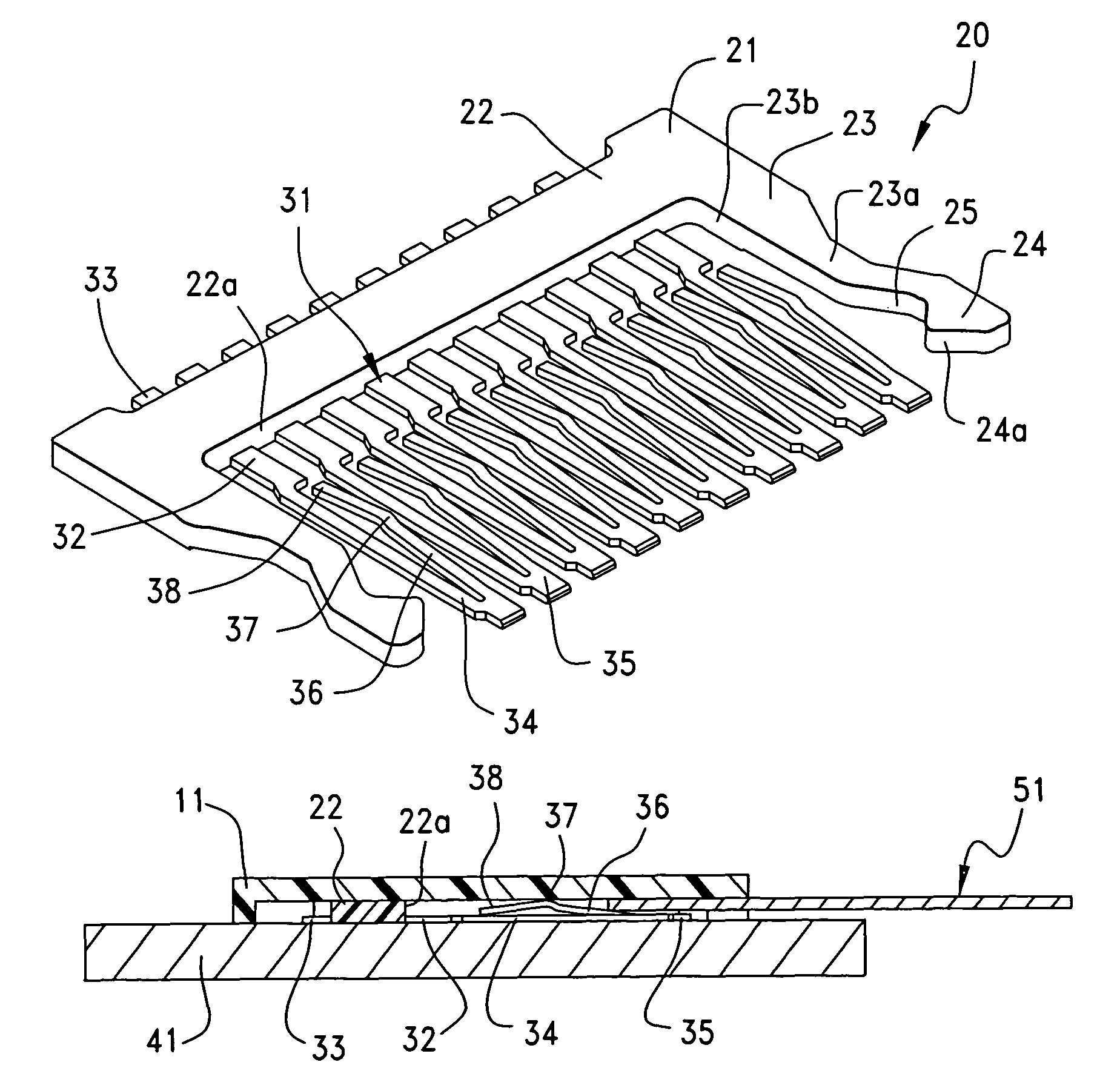
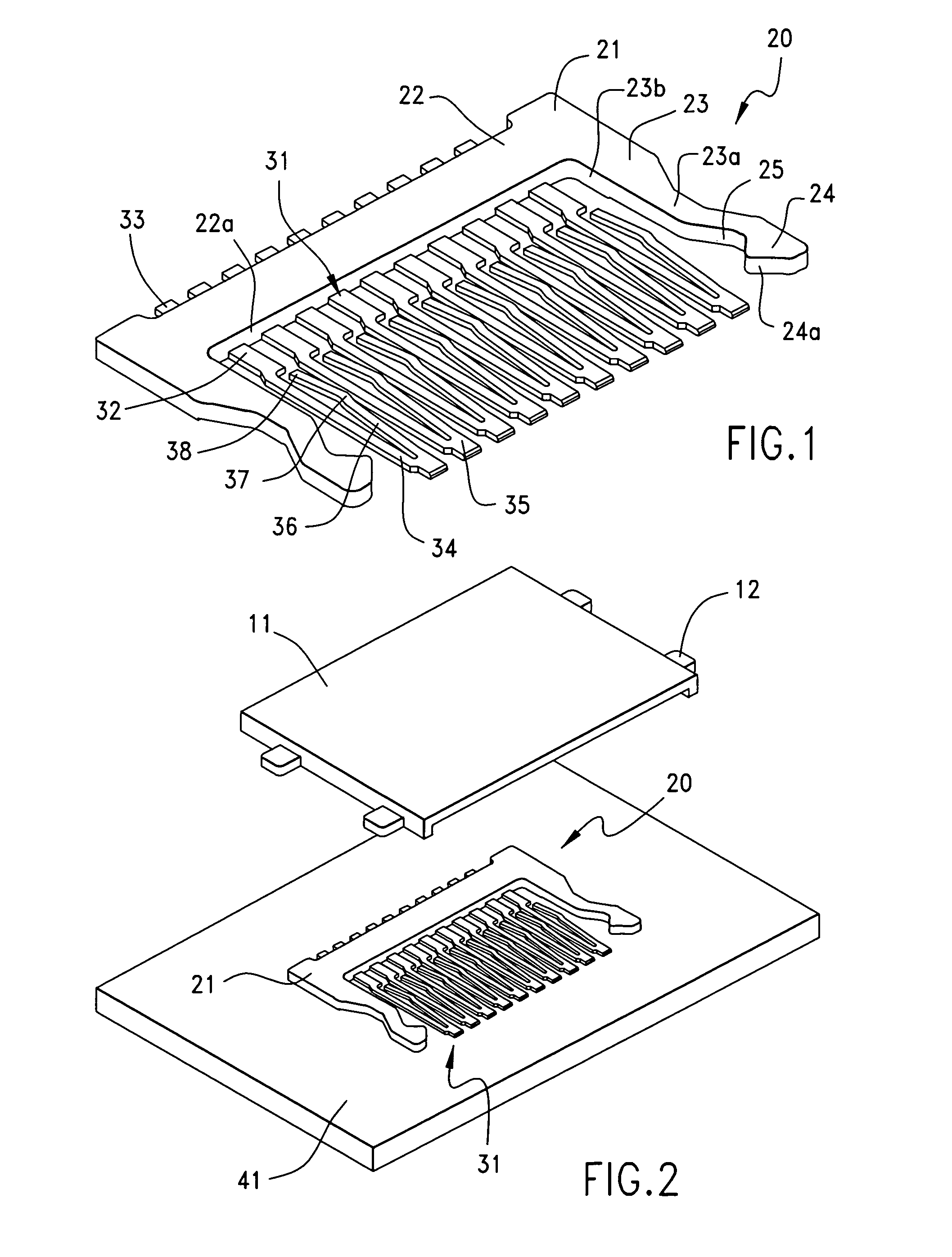
[0006]The present invention is directed to a flat cable connector that overcomes the aforementioned disadvantages and which maintains a low vertical profile. It is therefore an object of the present invention to provide a cable connector and a terminal therefor that permits easy insertion of a flat cable, and permits a reliable connection of the flat cable without causing disengagement thereof from the terminal, with a thin and simple structure while providing the terminal with such an improved configuration such that a front end portion and a rear end portion are arranged to be firmly secured to a substrate, and a free end arranged to be movable in a vertical direction with respect to a surface of the substrate, is disposed between the front end portion and the rear end portion.
[0014]In accordance with the present invention, a cable connector includes a terminal having a front end portion and a rear end portion which are firmly fixed to a substrate, and further having a free end that is movable in a vertical direction with respect to the surface of the substrate, the free end being disposed between the front end portion and the rear end portion. Hence, the cable connector can be thin and simple structure while permitting an easy insertion of the flat cable without causing abutment of the front end portion of the terminal against the flat cable, and also permitting a reliable connection of the flat cable without causing disengagement thereof from the terminal.

Problems solved by technology

This complicates the shape of the housing 301.

Method used


Image

  • Connector for connecting cable and terminal of same
  • Connector for connecting cable and terminal of same
  • Connector for connecting cable and terminal of same

Examples


Embodiment Construction

[0024]Preferred embodiments of the present invention will be described below in detail with reference to the accompanying drawings. The low vertical profile effected by connectors of the present invention make them particularly suitable for use in mobile telephones.

[0025]In FIG. 3, a cable connector 10 of the present invention is mounted on a substrate 41, such as a circuit board, and is used to electrically connect a flat cable (FFC / FPC) 51, as shown in FIG. 4 to a substrate.

[0026]In the preferred embodiment, it should be appreciated that the expressions indicating the directions, such as up, down, left, right, front, and rear, which are used to describe the constructions and operations of the cable connector 10 and the flat cable 51, are relative rather than absolute. These expressions are appropriate when the cable connector 10 and the flat cable 51 are in the position as shown in the drawing figures. However, when the attitudes of the cable connector 10 and the flat cable 51 are...


PUM


Abstract

A low profile flat printed circuit connector has a plurality of terminals supported along a support bar. The terminals are spaced apart from each other and extend lengthwise in a connector housing. The terminals have body portions that engage the support bar and body portions that extend forwardly thereof. Contact portions are joined to the body portions and extend rearwardly and terminate in free ends so that they form a series of cantilevered contacts.

Description

BACKGROUND OF THE INVENTION[0001]The present invention generally relates to a connector for connecting a length of flexible printed circuitry to an array of conductive terminals.[0002]In order to provide an electrical connection between flat flexible circuit cable, known as flexible printed circuit (FPC) or flexible flat cable (FFC) and terminals, FPC / FFC cables are known, such as that shown in Japanese Patent Application Laid-Open Application (Kokai) No. 10-116659. FIG. 8 is a cross-sectional view of a conventional cable connector.[0003]The conventional connector has a insulative housing 301 with a plurality of terminal holding spaces 302 partitioned by partitioning walls 307, and a plurality of terminals 303 that are formed of a conductive material such as metal, and are held within the terminal holding spaces 302. The terminals 303 have a U-shaped cross section, with solder tail parts 308 that are connected by soldering to conductive traces on a substrate 311.[0004]The housing 30...

Claims


Application Information

Patent Timeline
Patent Type & Authority Patents(United States)
IPC IPC(8): H01R24/00
CPCH01R12/79H01R12/7023H01R12/62H01R12/774H01R13/6273
Inventor HAYASHI, MASANORI
Owner MOLEX INC
Why Eureka
Eureka Blog
Learn More