Wheel sensor

Active Publication Date: 2013-11-26
SIEMENS MOBILITY GMBH
View PDF5 Cites 0 Cited by
  • Summary
  • Abstract
  • Description
  • Claims
  • Application Information

AI Technical Summary

Benefits of technology

[0009]Furthermore, the wheel sensor according to the invention has the advantage that the arrangement of the coils one above the other means that the housing length of the wheel sensor in the rail longitudinal direction can be utilized completely for each of the coils, that is to say both for the sensor coil and for the further coil. This allows the wheel rolling past to act over a particularly great length, thus resulting in the wheel sensor being particularly highly sensitive. This also applies in particular in the event of a lateral offset of the mass of iron to be detected caused by wheel flanges worn to different extents.
[0010]The wheel sensor according to the invention is preferably designed such that the further coil is arranged such that its longitudinal axis runs parallel to that of the sensor coil. Since the turn planes of the sensor coil and of the further coil are in this case parallel, or at least substantially parallel, to one another, this results in particularly good compensation

Problems solved by technology

This is a result of the fact that, if the distance between coils located one above the other were to be shorter, the mutual induction resulting from this would also result in virtually complete compensation even in the event of damping caused by a whee

Method used


Image

  • Wheel sensor
  • Wheel sensor

Examples


Embodiment Construction

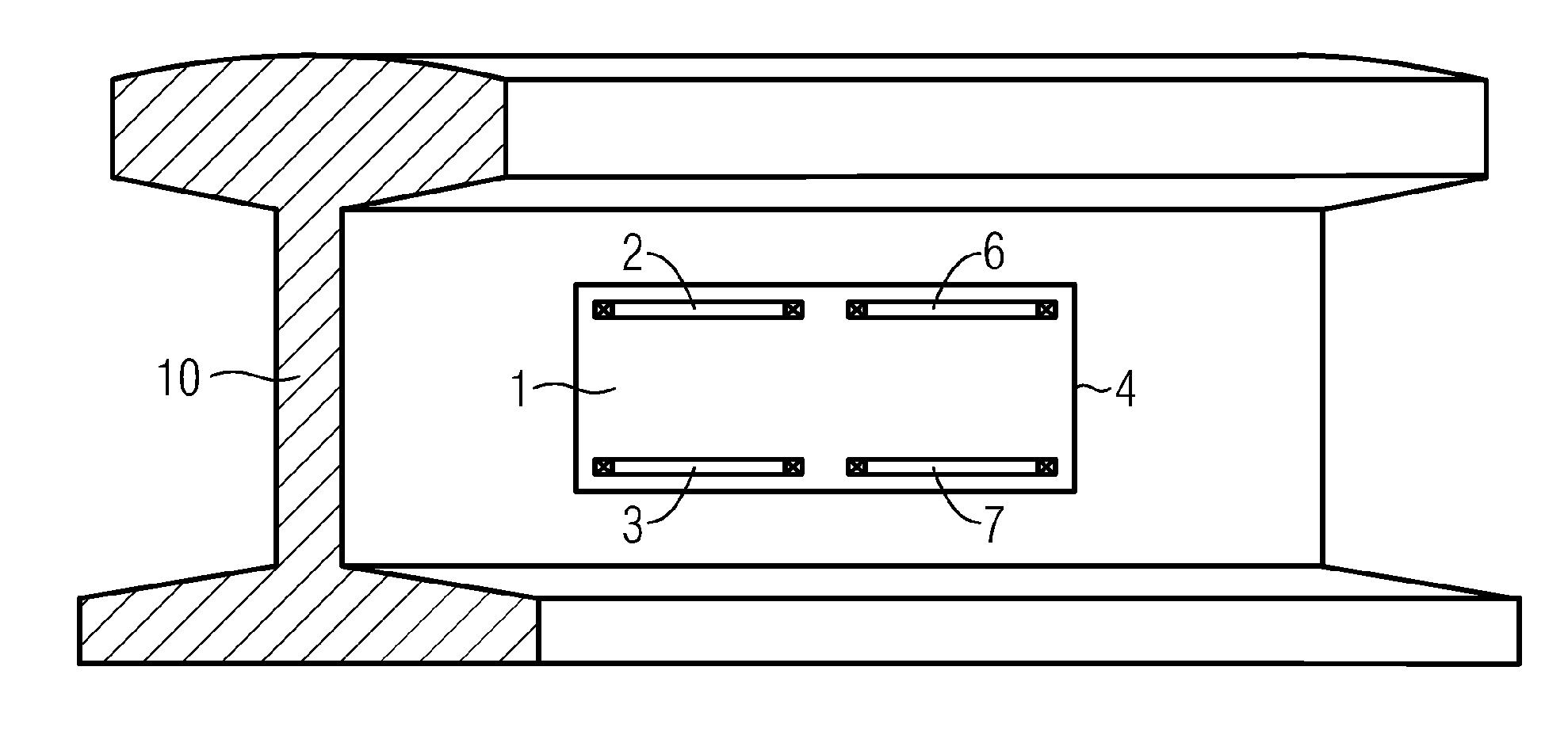
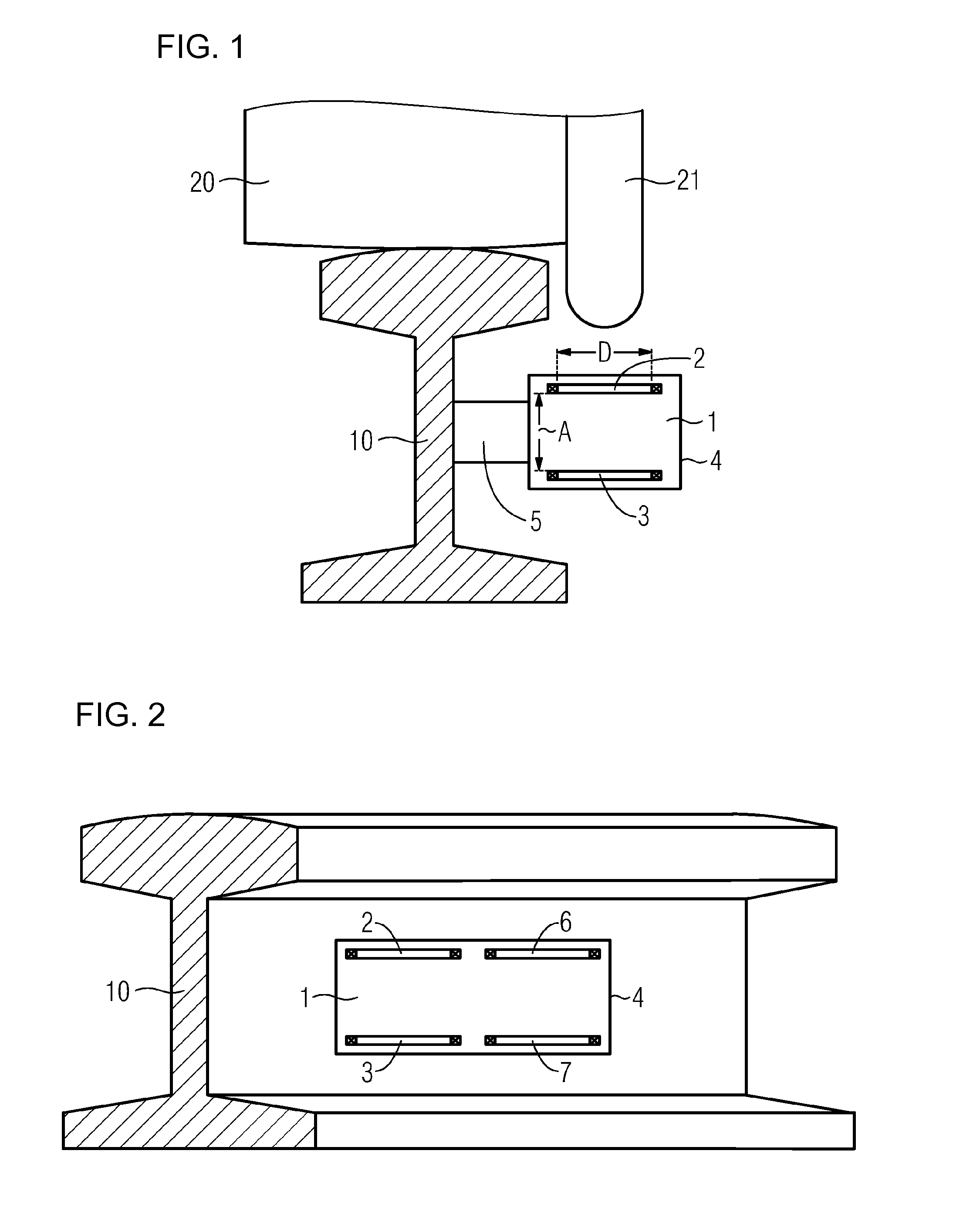
[0019]FIG. 1 shows a schematic sectional illustration of a first exemplary embodiment of a wheel sensor according to the invention fitted to the rail. The illustration is in the form of a section at right angles to the rail longitudinal direction and shows a wheel sensor 1 which has a sensor coil 2 and a further coil 3. The sensor coil 2 and the further coil are arranged in a housing 4 of the wheel sensor 1, with the wheel sensor 1, to be precise the housing 4 of the wheel sensor 1, being attached to a rail 10 by attachment means 5.

[0020]The sensor coil 2 is fed with an alternating current and is a component of a resonant circuit, which is sensitive to inductive interaction between the sensor coil 2 and wheels rolling past. Furthermore, the sensor coil 2 is connected in the opposite sense to the further coil 3 in order to suppress interference fields. For clarity reasons, neither the electrical components or connections mentioned above nor further components, known per se, of the wh...


PUM


Abstract

A wheel sensor that is particularly suited for track release signaling systems has at least one sensor device having an AC-fed sensor coil of an electric oscillating circuit sensitive to an inductive interaction of the sensor coil with passing wheels of rail vehicles. A further spool is connected to the sensor coil for suppressing external interference fields in a counter circuit. The further coil is arranged underneath the sensor coil and a spacing distance between the further coil and the sensor coil is at least one third of the inside diameter of the sensor coil.

Description

BACKGROUND OF THE INVENTIONField of the Invention[0001]Wheel sensors which operate on the principle of an inductive proximity switch are widely used in the field of railroad monitoring installations, in particular for track-free signaling installations. Corresponding wheel sensors have at least one sensor coil, which is arranged in an electrical resonant circuit and is fed with alternating current. The mass of iron in a wheel rolling past or in an axle rolling past leads to damping of the magnetic field of the sensor coil, as a result of which it is possible to detect that a wheel has moved past on the basis of a change caused by this in the characteristics of the electrical resonant circuit, for example the oscillation amplitude or the Q-factor.[0002]Inductively operating wheel sensors are normally comparatively sensitive to inductively input interference voltages at the operating frequency, such as those which can be caused by rail currents. By way of example, the return conductor...

Claims


Application Information

Patent Timeline
IPC IPC(8): B61L11/08B61L13/04
CPCB61L1/162B61L1/165
Inventor FREISE, RAINER
Owner SIEMENS MOBILITY GMBH
Why Eureka
Try Eureka