Eureka AIR delivers breakthrough ideas for toughest innovation challenges, trusted by R&D personnel around the world.

Programmable device for compressor valve

a compressor valve and programmable technology, applied in the direction of non-mechanical valves, process and machine control, instruments, etc., can solve the problem of high cos

Active Publication Date: 2013-11-19
SOUTHERN GAS ASSOC GAS MACHINERY RES COUNCIL
View PDF10 Cites 5 Cited by
  • Summary
  • Abstract
  • Description
  • Claims
  • Application Information

AI Technical Summary

Problems solved by technology

It costs a lot of money if a gas compressor valve is damaged and / or fails.

Method used


Image

  • Programmable device for compressor valve
  • Programmable device for compressor valve
  • Programmable device for compressor valve

Examples


Embodiment Construction

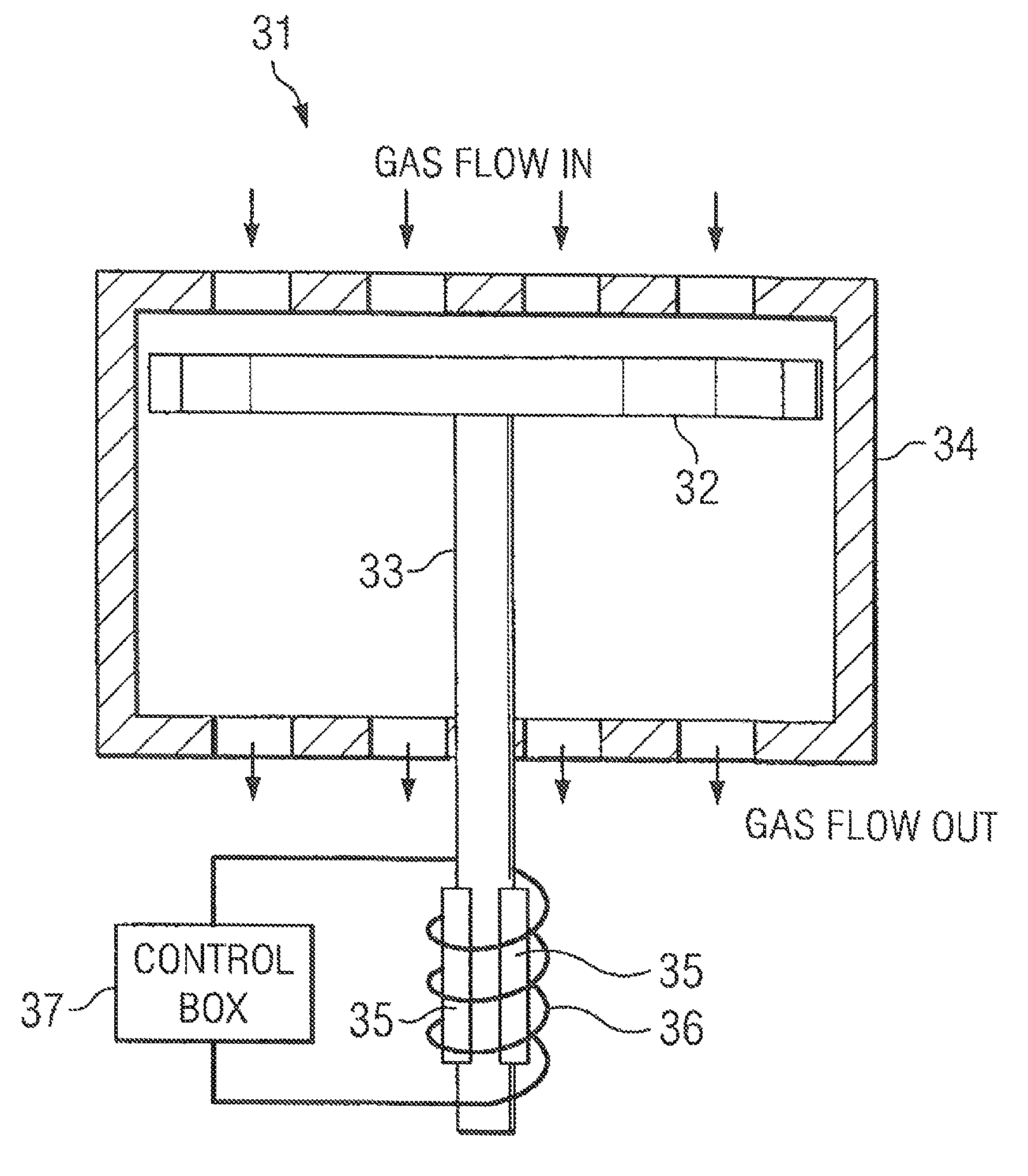
[0014]Sealing elements in the inlet and discharge valves of a reciprocating compressor may be moved to the open or closed position by forces imparted by the differential gas pressure to the movable sealing elements. The sealing elements may alternatively open and close with each stroke of the compressor in order to permit gas flow in one direction but block gas flow in the reverse direction. Methods and a device for controlling valve elements though the use of algorithms installed in a programmable control device is provided.

[0015]To date, very little has been done to manage the motion of the compressor valve elements. Spring systems, damper plates, and a variety of different geometries can be introduced to slow plate motion or change the timing of certain events, but the forces from the differential gas pressure on each side of the valve often prevent these devices from achieving effective, long term control. Gas forces are the most dominant force affecting valve element motion. Cu...


PUM


Abstract

An electronic, programmable device for controlling the motion of compressor valve elements, wherein the device receives an incoming signal from a velocity sensor located on a compressor valve; filters, amplifies, and processes the incoming signal by a control algorithm; and responds to the incoming signal by creating an output signal that produces an actuator force that is applied directly to a moving valve element and associated methodology.

Description

CROSS-REFERENCE TO RELATED APPLICATIONS[0001]This application claims priority to U.S. patent application Ser. No. 61 / 045,193 filed Apr. 15, 2008 which is incorporated by reference herein in its entirety.STATEMENT REGARDING FEDERALLY SPONSORED RESEARCH OR DEVELOPMENT[0002]None.THE NAMES OF THE PARTIES TO A JOINT RESEARCH AGREEMENT[0003]None.REFERENCE TO SEQUENCE LISTING[0004]None.BACKGROUND OF THE INVENTION[0005]In order to transport gases over great distances, pipeline and oil companies operate and maintain hundreds of thousands of miles of pipelines. Compressed gases are needed to take part in chemical reactions in refineries and petrochemical plants. To provide forces that move and compress the gases, operators install gas compressors at key points in the process chain The gas compressors are typically reciprocating compressors. It costs a lot of money if a gas compressor valve is damaged and / or fails.SUMMARY OF THE INVENTION[0006]An electronic, programmable device for controlling...

Claims


Application Information

Patent Timeline
Patent Type & Authority Patents(United States)
IPC IPC(8): F16K31/02F01L9/20
CPCF01L9/04F01L2009/049Y10T137/0971Y10T137/7761F01L2009/409F01L9/20
Inventor BRUN, KLAUSCONVERSE, MERLE E.HELFFRICH, JEROME A.
Owner SOUTHERN GAS ASSOC GAS MACHINERY RES COUNCIL
Why Eureka
Eureka Blog
Learn More