
Movement control screed

a movement control and screed technology, applied in the direction of resiliently-mounted floors, walls, flooring, etc., can solve the problems of rotting of wooden structures within the wall, moisture can get behind the masonry coating at improperly sealed joints,

Active Publication Date: 2013-11-19
ALABAMA METAL INDS
View PDF97 Cites 30 Cited by
  • Summary
  • Abstract
  • Description
  • Claims
  • Application Information

AI Technical Summary

Benefits of technology

This patent describes a movement control screed that can be used between two layers of masonry on a building wall. The screed acts as both an expansion control joint and a weep screed, meaning it can adapt to changes in the wall and drain moisture. The screed has ribs that allow it to move and accommodate movements between wall sections, reducing cracks in the masonry coatings. The screed can also have a water resistant layer to encourage moisture to flow over it and not behind it. In summary, this patent provides a solution for controlling movement and managing moisture in building walls.

Problems solved by technology

Moisture can get behind the masonry coating at improperly sealed joints (e.g., at doors or windows) or because of cracks that may form in the masonry coating.
If left unchecked, such moisture may cause rotting of wooden structures within the wall.

Method used


Image

  • Movement control screed
  • Movement control screed
  • Movement control screed

Examples


example embodiments

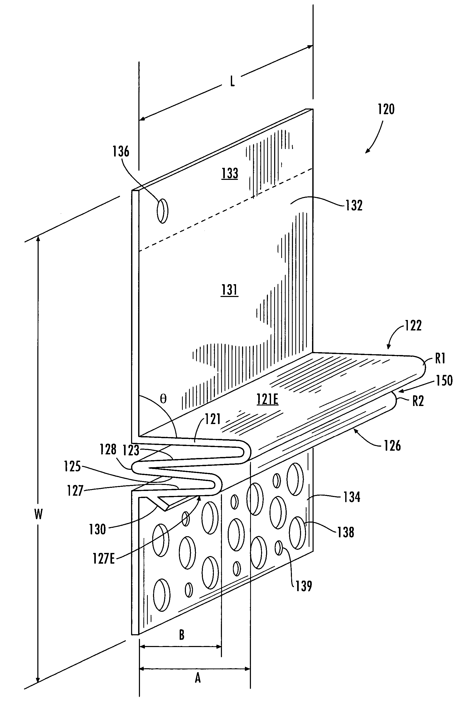
[0039]FIG. 5 depicts a side view of a movement control screed for illustrating a few selected dimensions taken from several exemplary movement control screeds. Numerical values for the selected dimensions are provided in Table 1 below for illustration purposely only. The precise dimensions of movement control screeds according to various embodiments of the present invention may vary from application to application as will be apparent to one of ordinary skill in the art. Thus, although numerous examples are provided in Table 1 below, multiple additional embodiments of the present invention may include dimensions and numerical values that are not listed in Table 1. The dimensions selected for Table 1 include an exemplary movement control screed width W, a first rib position X, a second rib position Z, and a channel width Y. Exemplary values for a first screed depth A and a second screed depth B are also provided. Notably, the exemplary values for A and B may be reversed to satisfy emb...


PUM


Abstract

Various embodiments of the present invention are directed to a movement control screed that is structured for installation between first and second masonry coatings applied adjacent to a building wall. The movement control screed is structured as a control joint for absorbing movement between the first and second masonry coatings and also as a weep screed for accommodating drainage of water from behind the masonry coatings. The movement control screed comprises first and second flanges provided on opposite sides of first and second ribs.

Description

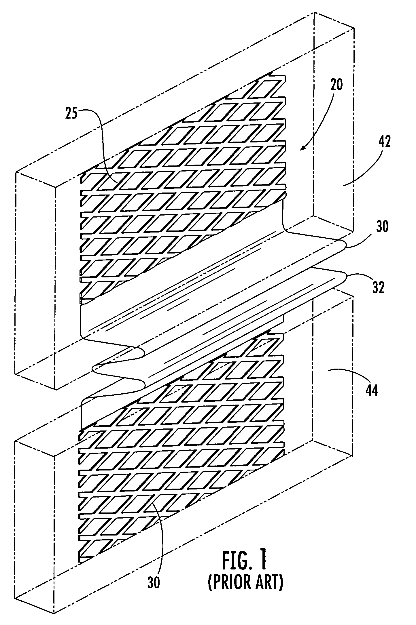
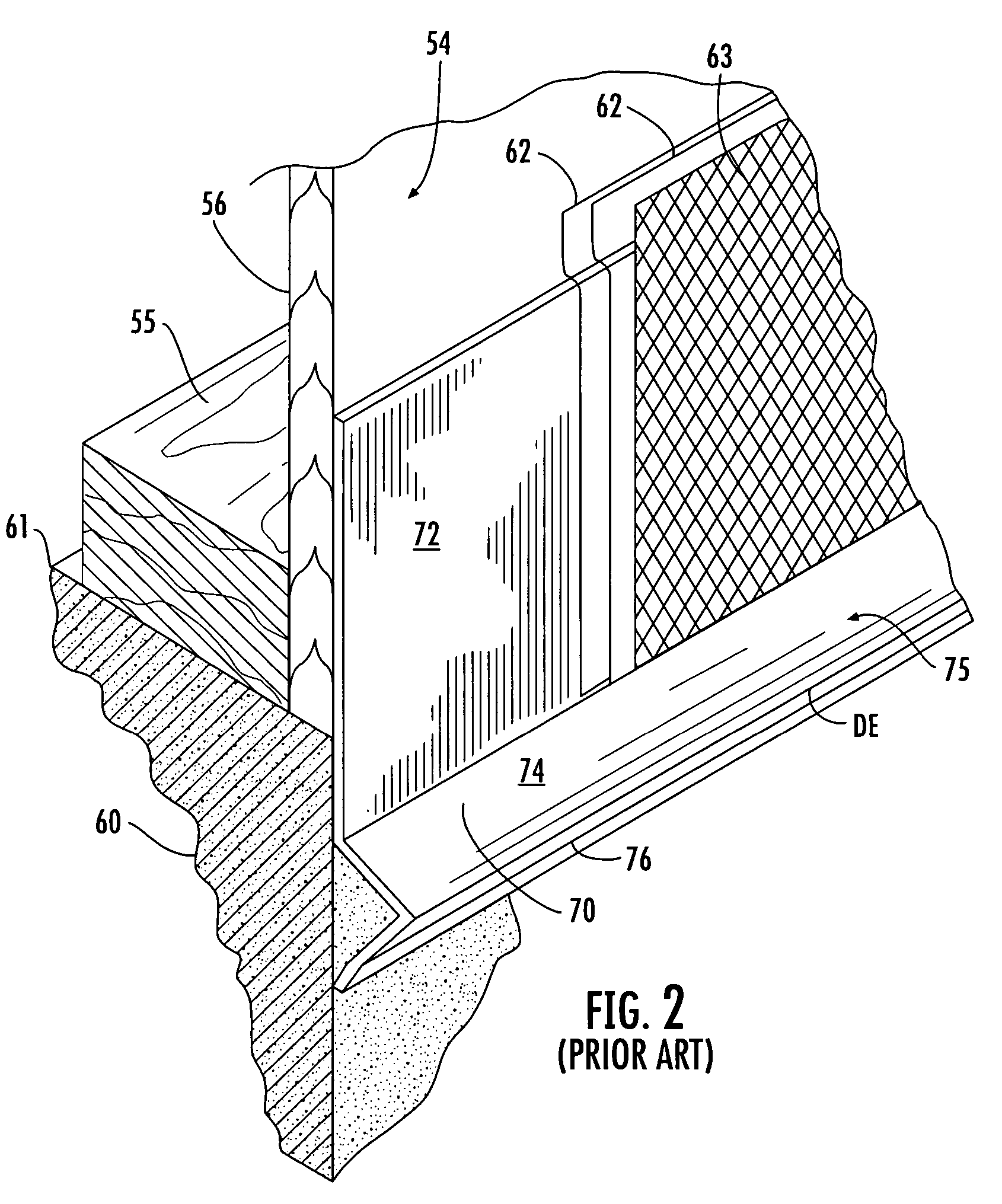
BACKGROUND OF THE INVENTION[0001]1. Field of the Invention[0002]The present invention relates to building construction devices that provide drainage and reduce cracks within masonry coatings such as stucco. More specifically, the present invention relates to an improved movement control screed that is structured to operate as a control joint for absorbing movement in a masonry coating and also as a weep screed to provide drainage of water from within and behind the masonry coating.[0003]2. Description of Related Art[0004]Expansion control joints and foundation weep screeds are commonly known in the masonry construction arts. FIG. 1 depicts an exemplary expansion control joint 20 in accordance with the known prior art. Expansion control joints are used to break up large areas intended for receiving masonry coatings such as plaster, stucco, and the like, into smaller masonry coated areas for purposes of relieving stress and resisting cracking. The depicted expansion control joint 20 i...

Claims


Application Information

Patent Timeline
Patent Type & Authority Patents(United States)
IPC IPC(8): E04B1/62E04B1/68E04F15/14E04B1/343
CPCE04F13/06E04F2013/066
Inventor CHENIER, GARYSOUTHERN, MICHAEL
Owner ALABAMA METAL INDS
Learn More