
System and method to account for thermal die expansion

a technology of thermal die and system, applied in the direction of auxillary shaping apparatus, ceramic shaping apparatus, manufacturing tools, etc., can solve the problems of thermal expansion, thermal expansion of casting die, thermal expansion, etc., and achieve the effect of easy and cost-effective retrofitting

Inactive Publication Date: 2013-11-12
HONDA MOTOR CO LTD
View PDF27 Cites 0 Cited by
  • Summary
  • Abstract
  • Description
  • Claims
  • Application Information

AI Technical Summary

Benefits of technology

The patent describes a system and method that controls the adjustment of the height of a movable platen in die casting machines. This is achieved by calculating the distance of the movable platen from the rotational motion of an idler gear. This new system is easier and cheaper to install than existing systems, and it provides a better solution for adjusting the die height in existing machines. The technical effect of this patent is to offer a more efficient and cost-effective solution for adjusting the die height in die casting machines.

Problems solved by technology

A problem associated with die casting processes is thermal expansion of a casting die.
Generally, however, the repeated formation of work pieces by the introduction of molten metal into a casting die increases the die temperature and leads to the thermal expansion thereof.
While the extent of this thermal expansion may not seem significant from a purely dimensional standpoint, the die growth can nonetheless be sufficient to negatively affect or interfere with proper casting machine operation.
More specifically, after die expansion, the previously set clamping position of the movable platen may result in excessive pressure on the casting die, which can lead to excessive force being exerted on the die, increased strain on the tie bars, and / or other problems.
This is time consuming and performed outside full automatic operation of the die casting machine.
However, such an automated feature was not generally available on older die casting machines.
While it is sometimes possible to retrofit such a system to an older die casting machine, doing so is typically a costly option that must be purchased from the original equipment manufacturer.
Known automated die height adjustment systems available from the various original equipment manufacturers are generally quite complex, utilizing encoders, linear scales, specialized controllers and specialized programming.
Further, the electrical components of the original casting machines become obsolete, frequently requiring that they also be upgraded, redesigned or modified in order to accommodate a retrofit die height adjustment system.
This also adds cost to such a retrofit.

Method used


Image

  • System and method to account for thermal die expansion
  • System and method to account for thermal die expansion
  • System and method to account for thermal die expansion

Examples


Embodiment Construction

)

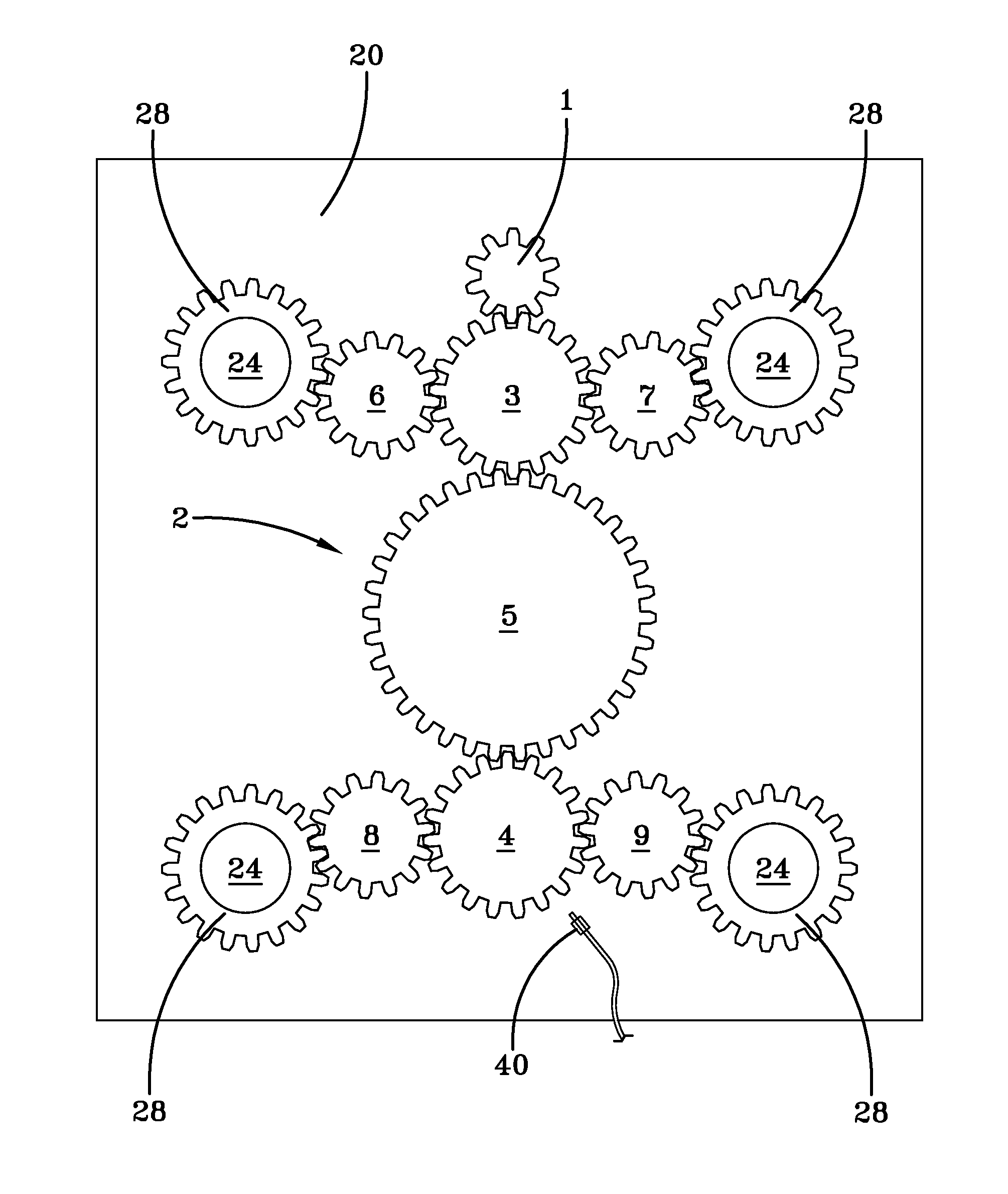
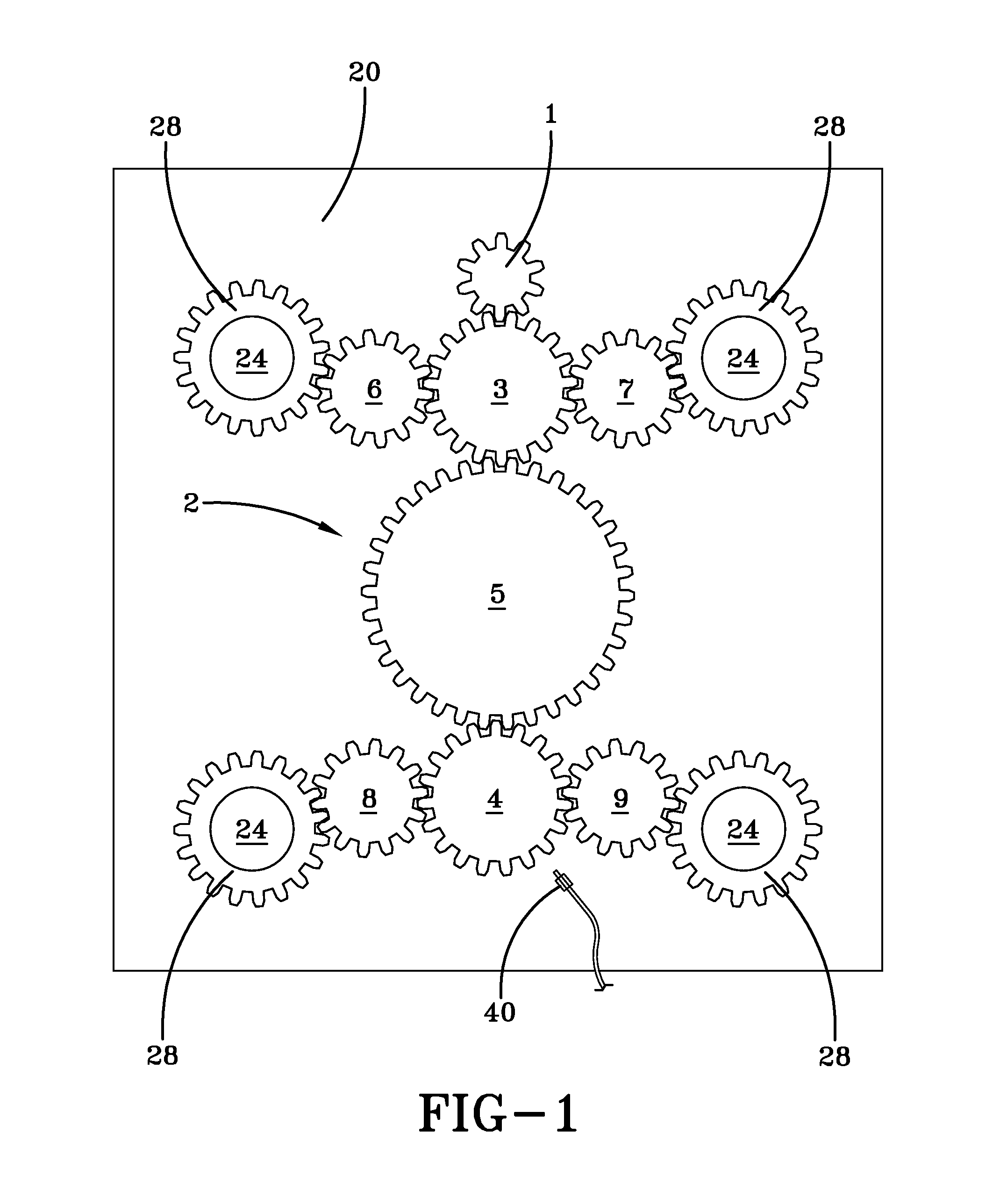
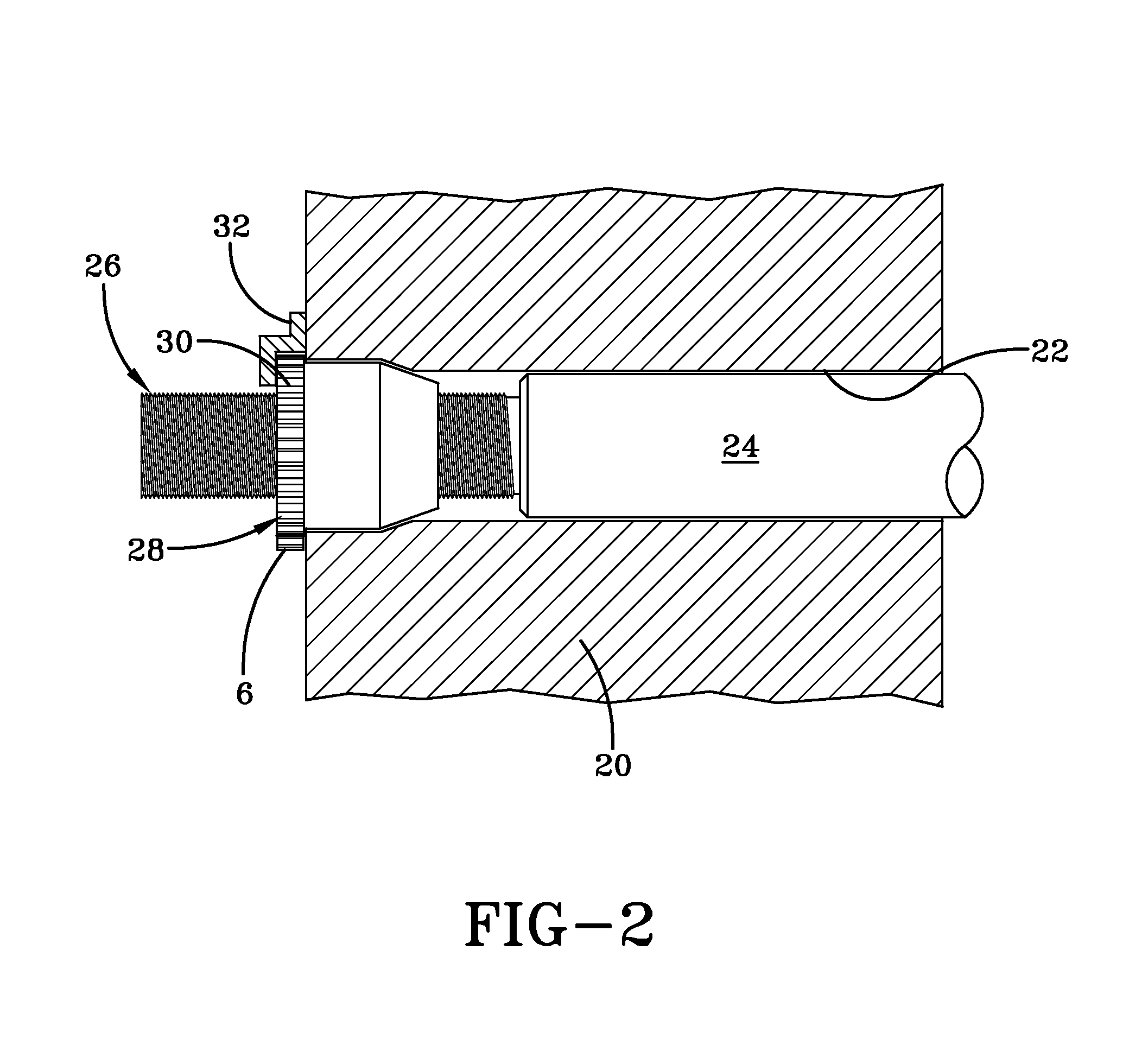
[0013]A movable platen and various related components of an exemplary die casting machine that may benefit from the system and method described herein is illustrated in FIG. 1 and FIG. 2. As shown, the die casting machine includes a movable platen 20, which moves along a plurality of tie bars 24, and a gear train 2 of rotatable clears that is associated with a non-die side of the movable platen. A drive motor / input gear 1 is provided to rotationally drive the gear train, which also includes a series of intermeshed idler gears 3-9 that are rotatably affixed to the back of the movable platen 20.

[0014]More specifically, the gear train 2 of this exemplary die casting machine includes a central idler gear 5 located substantially equidistantly between the plurality of tie bars 24 that pass through the movable platen 20, a second pair of idler gears 3, 4 that are intermeshed with and located on opposite sides of the central idler gear and substantially in line with a rotational axis there...


PUM

PropertyMeasurementUnit
linear displacementaaaaaaaaaa
linear travel distanceaaaaaaaaaa
travel distanceaaaaaaaaaa

Abstract

A system and method for effecting die height adjustments of a casting machine, such as to account for thermal die expansion. The system and method finds use on a die casting machine having a driven gear train for causing linear movement of a movable platen thereof. Based on known characteristics of the gears of the gear train and of threaded tie bar nuts upon which the gear train operates, a given rotation of a gear train gear can be converted into a linear movement of the movable platen. A sensor is used to count the teeth of a rotating gear train gear and a controller is provided to correlate the tooth count with a corresponding linear travel distance of the movable platen.

Description

TECHNICAL FIELD[0001]The invention described herein relates to a system and method for performing automatic die height adjustments. More specifically, the invention described herein relates to a system and method that permits a casting machine to compensate for thermal die expansion.BACKGROUND[0002]A die casting machine generally comprises a stationary platen and a movable platen. The stationary platen is fitted with a stationary die half. The movable platen is fitted with a movable die half. The movable platen is aligned with the stationary platen by tie bars. The movable platen can be advanced toward and away from the stationary die along these tie bars. Movement of the movable platen toward and away from the stationary platen during machine operation may be accomplished by hydraulic cylinder, a toggle clamping linkage, etc., as would be familiar to one of skill in the art.[0003]A problem associated with die casting processes is thermal expansion of a casting die. Thermal die expa...

Claims


Application Information

Patent Timeline
Patent Type & Authority Patents(United States)
IPC IPC(8): B29C45/80
CPCB22D17/32
Inventor STEINER, MICHAEL R.
Owner HONDA MOTOR CO LTD
Learn More