
Separating device

Active Publication Date: 2013-11-12
HANSEN BERND
View PDF14 Cites 0 Cited by
  • Summary
  • Abstract
  • Description
  • Claims
  • Application Information

AI Technical Summary

Benefits of technology

[0008]An object of the invention is to provide an improved separating device with which the container products, regardless of the plastic material forming them,

Problems solved by technology

This delay would necessarily lead to very long retention sections and/or require additional cooling for the container products to be separated in order to be able to undertake separ

Method used


Image

  • Separating device
  • Separating device
  • Separating device

Examples


Example

[0025]In some of the figures, components of the overall device are omitted for purposes of clarity of the solution according to the invention.

DETAILED DESCRIPTION OF THE INVENTION

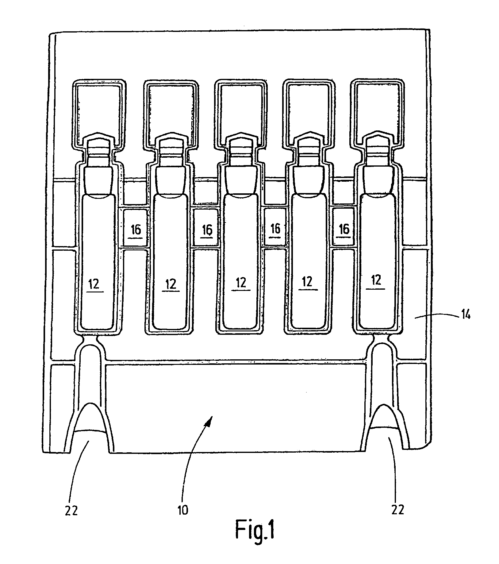
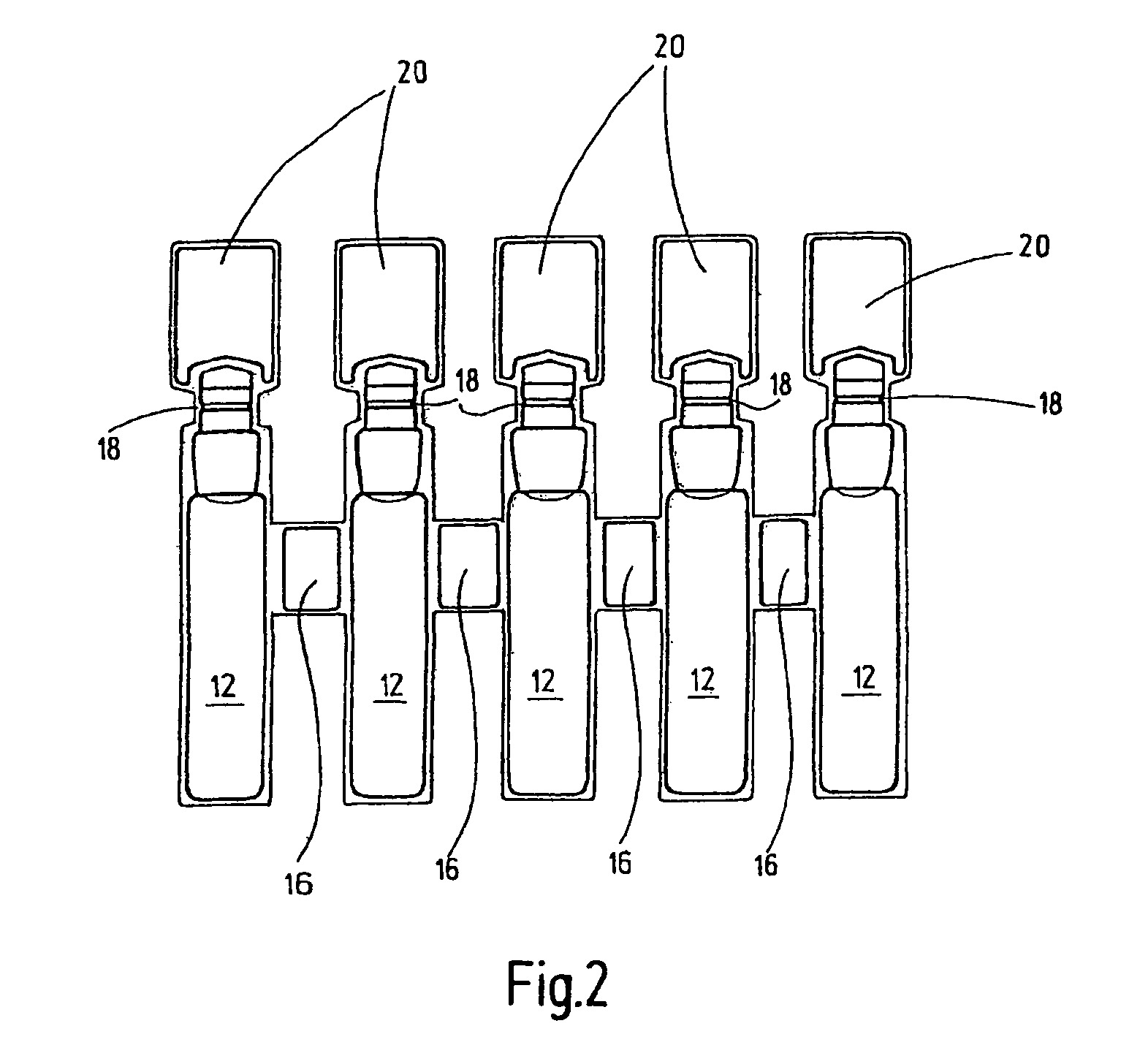
[0026]The frame assemblage 10 shown in FIG. 1 is formed of a plastic material, in this case of a polypropylene material. The frame assemblage 10 is composed essentially of the actual container products 12 and the frame waste 14 which can be separated from the actual container products 12. When the container products 12 are separated from the frame waste 14, an ampule block from which the frame waste 14 has been removed as shown in FIG. 2 results. The individual containers or individual ampules 12 are detachably connected to one another by the remaining intermediate wall webs 16 of the frame waste 14, the intermediate wall webs 16 making it possible for the respective container product 12 to be separated from the other containers 12 remaining in the block in a twist-off motion.

[0027]The respective container ...


PUM

PropertyMeasurementUnit
Speedaaaaaaaaaa
Energyaaaaaaaaaa
Plasticityaaaaaaaaaa

Abstract

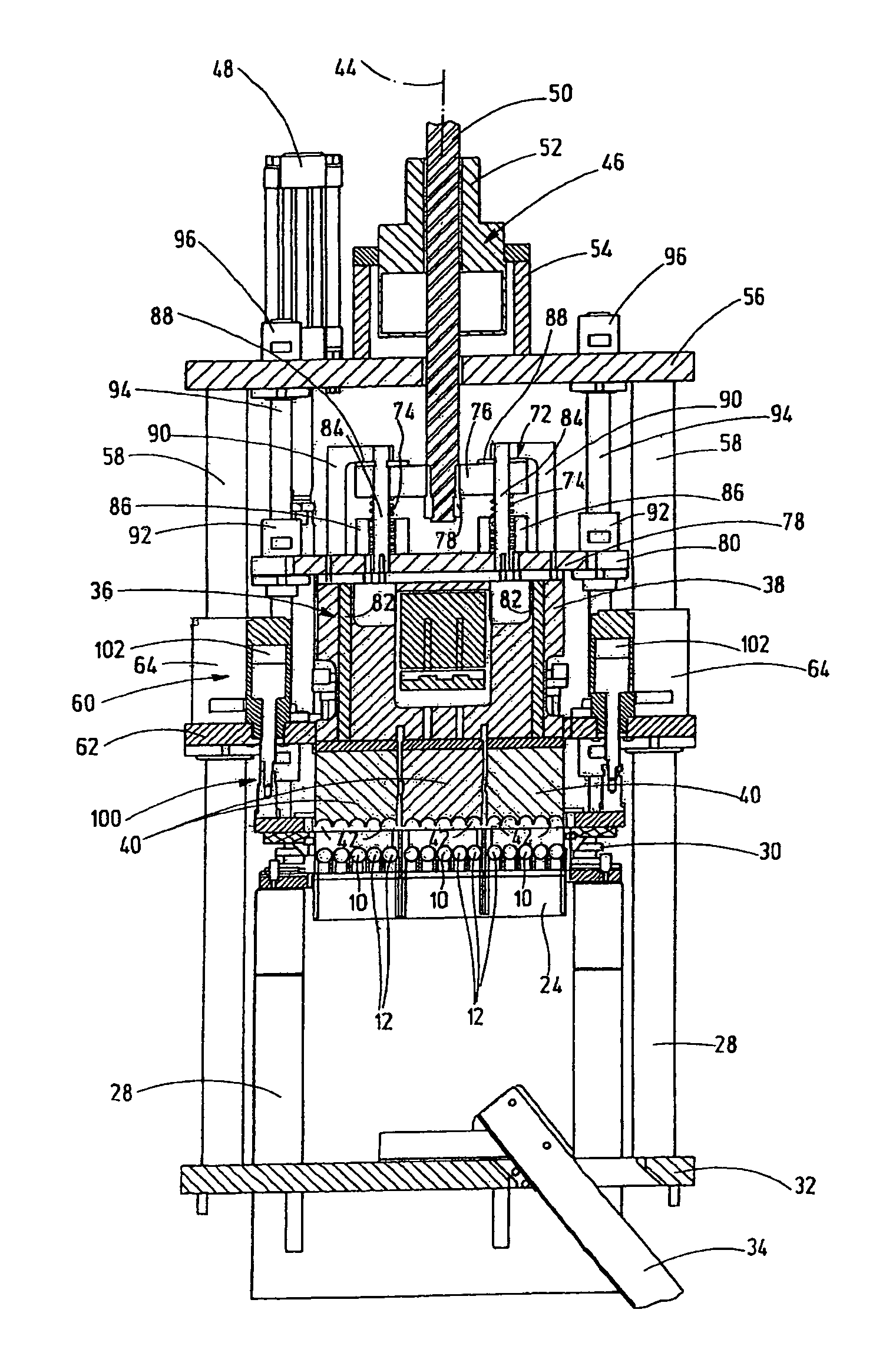
A separating device for cutting off individual containers (12) from a frame network made of a plastic material, particularly of polypropylene, has at least one punching device at least partially separating the containers (12) from a waste frame. Because the punching device can be moved by a ball screw drive (46) that can be driven by a drive unit, particularly in the form of an eclectic motor (48), along a punching axis (44) from a starting position to a punching position and back again, the separation can be done at high speed, determined by the screw shaft that can be driven by the electric motor.

Description

FIELD OF THE INVENTION[0001]The invention relates to a separating device for separating individual container products from a frame assemblage of a plastic material, particularly polypropylene, with at least one punching device which at least partially separates the container product from the frame waste.BACKGROUND OF THE INVENTION[0002]The prior art (DE 199 26 329 A1) discloses methods and devices for producing container products from plastic, how they are supplied to a generic separating device which is then used to separate these individual container products from a frame assemblage using a cutting or punching device.[0003]To produce the respective container product, first a tube of plasticized plastic material is extruded into a molding device. One end of the tube is closed by heat sealing and by producing a pneumatic pressure which acts on the tube. The tube is expanded forms the container by being placed against the forming wall of the molding device of two opposite molding too...

Claims


Application Information

Patent Timeline
IPC IPC(8): B29C49/72B26F1/02B26D5/08
CPCB26D7/0006B26F1/40B29C49/0047B29C49/72B29K2023/0641B29K2023/12Y10T83/8821Y10T83/8847Y10T83/9423Y10T83/8824B29C49/0691B29C49/48185
Inventor HANSEN, BERND
Owner HANSEN BERND
Learn More