
Digital video recording system

a video recording and digital technology, applied in the field of digital video recording systems, can solve the problems of lowering the value of the solution, unable to capture and play back information at the same time, and expensive equipment becomes unreliable, difficult to operate, and unreliable,

Inactive Publication Date: 2013-11-05
TIVO SOLUTIONS INC
View PDF440 Cites 8 Cited by
  • Summary
  • Abstract
  • Description
  • Claims
  • Application Information

AI Technical Summary

Benefits of technology

Enables efficient recording and playback of TV programs with lower system costs, improved user control, and integration of DVD technology for enhanced storage and playback capabilities, while maintaining cost-effectiveness and supporting advanced features like copyright protection.

Problems solved by technology

However, a VCR cannot both capture and play back information at the same time.
Continuing this exercise, one can quickly see that the equipment becomes unwieldy, unreliable, expensive, and hard to operate, while never supporting all desired functions.
In addition, tapes are of finite length, and may potentially end at inconvenient times, drastically lowering the value of the solution.
However, this approach is difficult to implement because the processor requirements for keeping up with the high video rates makes the device expensive and problematic.
However, a typical recordable DVD can only store approximately five GBs of data.
However, these approaches do not take advantage of the recordable DVD and further do not take advantage of storing large amounts of information on a hard disk.

Method used


Image

  • Digital video recording system
  • Digital video recording system
  • Digital video recording system

Examples


Embodiment Construction

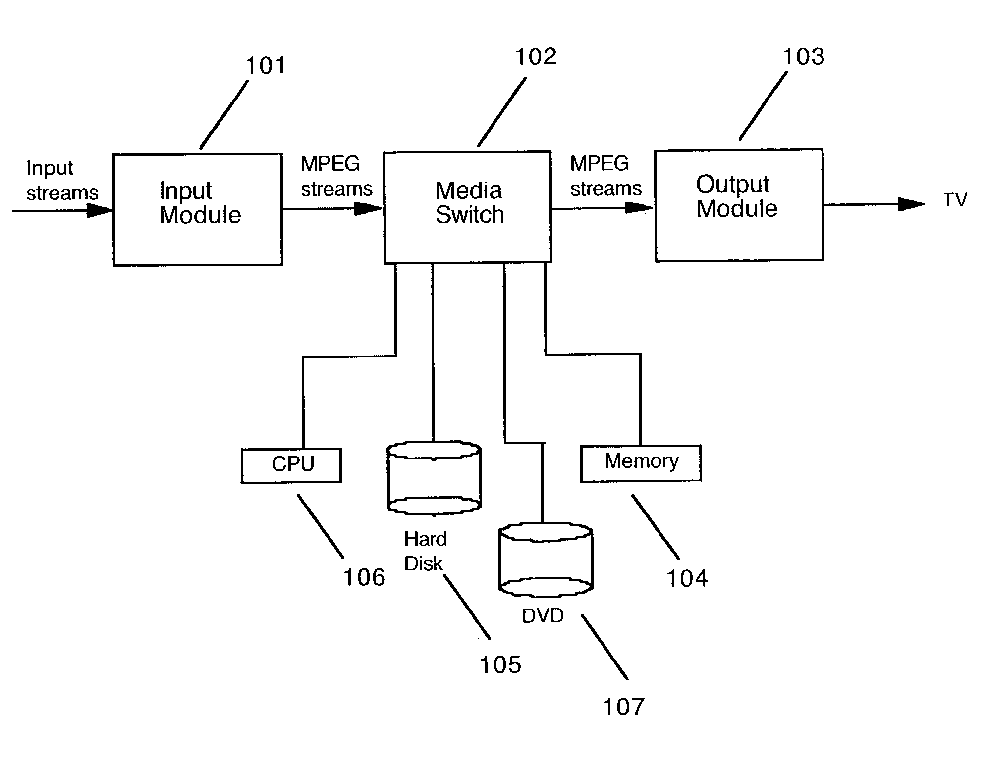
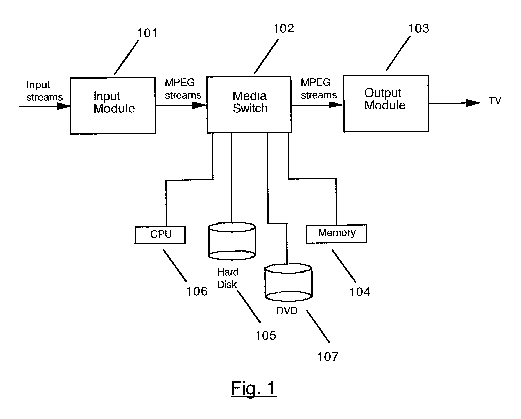
[0040]The invention is embodied in a digital video recorder system with an integrated DVD recording device. A system according to the invention gives a user the ability to record and play back TV broadcast programs and digital video in a set-top box. The invention additionally integrates a recordable DVD into the set-top box for backing up, transferring, and playing recorded program material.

[0041]Referring to FIG. 1, a preferred embodiment of the invention has an Input Section 101, Media Switch 102, and an Output Section 103. The Input Section 101 takes television (TV) input streams in a multitude of forms, for example, National Television Standards Committee (NTSC) or PAL broadcast, and digital forms such as Digital Satellite System (DSS), Digital Broadcast Services (DBS), or Advanced Television Standards Committee (ATSC). DBS, DSS and ATSC are based on standards called Moving Pictures Experts Group 2 (MPEG2) and MPEG2 Transport. MPEG2 Transport is a standard for formatting the di...


PUM

PropertyMeasurementUnit
timeaaaaaaaaaa
timeaaaaaaaaaa
timeaaaaaaaaaa

Abstract

A digital video recorder (DVR) system with an integrated DVD recording device accepts TV input streams in a multitude of forms. Analog TV streams are converted to an MPEG formatted stream for internal transfer and manipulation, while pre-formatted MPEG streams are extracted from the digital TV signal and presented in a similar format. Indexes within the MPEG stream are determined and saved at predefined intervals and are stored on a hard disk along with the MPEG program material and used to create navigation packets when writing to a DVD inserted in an integrated DVD player / recorder. When a program is requested for display from the hard disk or the integrated DVD player / recorder, the program material are extracted from the appropriate source and reassembled into an MPEG stream which is sent to a decoder. The decoder converts the MPEG stream into TV output signals and delivers the TV output signals to a TV monitor. User control commands are accepted which affect the flow of the MPEG stream allowing the user to view stored programs with special functions: reverse, fast forward, play, pause, index, fast / slow reverse play, and fast / slow play. The user can select program material stored on the hard disk to be written to a DVD and can also select program material stored on a DVD to be transferred to the hard disk.

Description

CROSS REFERENCE TO RELATED APPLICATIONS[0001]This application is a Continuation-in-part of U.S. patent application Ser. No. 09 / 827,029, filed on 5 Apr. 2001 which is a continuation of U.S. Pat. No. 6,233,389 filed on 30 Jul. 1998; this application further claims benefit of U.S. Provisional Patent Application Ser. No. 60 / 374,101, filed on 19 Apr. 2002.BACKGROUND OF THE INVENTION[0002]1. Technical Field[0003]The invention relates to the time shifting of television broadcast signals. More particularly, the invention relates to the real time capture, storage, and display of television broadcast signals and the transfer and playback of said television broadcast signals from a DVD player / recorder.[0004]2. Description of the Prior Art[0005]The Video Cassette Recorder (VCR) has changed the lives of television (TV) viewers throughout the world. The VCR has offered viewers the flexibility to time shift TV programs to match their lifestyles.[0006]The viewer stores TV programs onto magnetic tap...

Claims


Application Information

Patent Timeline
Patent Type & Authority Patents(United States)
IPC IPC(8): H04N5/76H04N5/917H04N5/765H04N7/16H04N5/93H04N9/80G11B27/00G11B27/024G11B27/031G11B27/032G11B27/034G11B27/10G11B27/11G11B27/32G11B27/34H04N5/775H04N5/781H04N5/85H04N9/79H04N9/804H04N9/806
CPCG11B27/329G11B27/34H04N5/4401H04N5/76H04N5/775H04N5/782H04N21/4147H04N21/42204H04N21/42615H04N21/4263H04N21/4307H04N21/432H04N21/4334H04N21/4341H04N21/4344H04N21/4345H04N21/4402H04N21/440281H04N21/4532H04N21/454H04N21/472H04N21/47214H04N21/4884H04N21/8456H04N21/8547G11B27/031G11B27/034G11B27/105G11B27/11G11B27/3027G11B27/3054G11B20/10527H04N9/8081G11B2220/216G11B2220/218G11B2220/2516G11B2220/2562G11B2220/2575G11B2220/41G11B2220/455G11B2220/90H04N5/781H04N5/85H04N9/7921H04N9/8042H04N9/8063G11B27/002G11B27/024G11B27/032H04N21/426H04N21/43072
Inventor BARTON, JAMES M.MOSKOWITZ, ALANGOODMAN, ANDREW MARTIN
Owner TIVO SOLUTIONS INC
Learn More