
Method of controlling an electronic display and an apparatus comprising an electronic display

a technology of electronic display and electronic display, applied in the direction of electric digital data processing, instruments, computing, etc., can solve the problems of increasing power consumption, shortening the product life, and visible white and black particles, and achieve the effect of compromising robustness and not increasing the frame ra

Inactive Publication Date: 2013-11-05
SAMSUNG ELECTRONICS CO LTD
View PDF6 Cites 0 Cited by
  • Summary
  • Abstract
  • Description
  • Claims
  • Application Information

AI Technical Summary

Benefits of technology

This approach allows for higher bit depth and robust grey level generation without increasing frame rates, reducing power consumption and improving image reproducibility while maintaining image quality and contrast.

Problems solved by technology

Addressing such electrophoretic display for a short time with a certain voltage will result in a situation that a mixture of white and black particles is visible.
Increasing the frame rate generally increases power consumption and potentially leads to a shorter product lifetime.

Method used


Image

  • Method of controlling an electronic display and an apparatus comprising an electronic display
  • Method of controlling an electronic display and an apparatus comprising an electronic display
  • Method of controlling an electronic display and an apparatus comprising an electronic display

Examples


Embodiment Construction

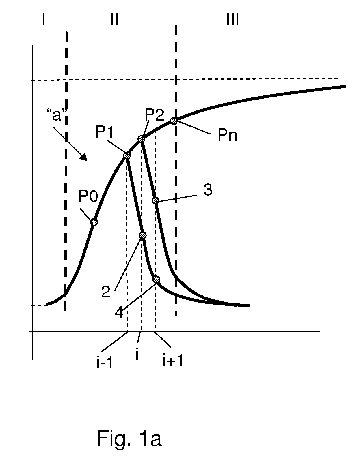
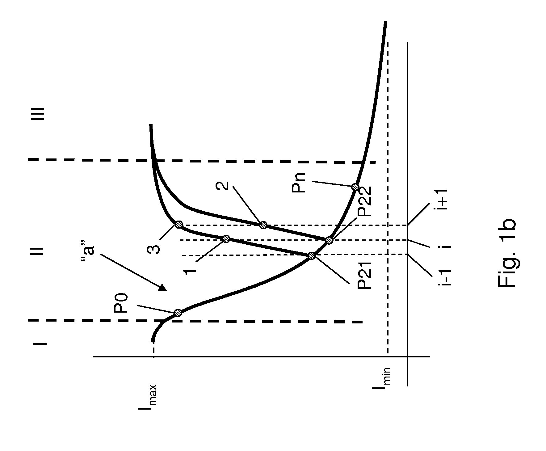
[0027]FIG. 1a presents a schematic view of a typical reflectivity curve for an electrophoretic display when changing from black to white. A reflection curve “a” has three identifiable regions. Initially, in a region I, a relatively slow change of the reflection occurs, i.e. low derivative. After a certain percentage of the reflection is reached in region II, a change in reflection per applied voltage (abscissa) may have a steep portion, characterized by an increased derivative. Finally, in region III close to a maximum reflection level Imax, a change in reflection may decrease again, i.e. lower derivative. It is understood that in the case where a control voltage is alternated to a control voltage of an opposite polarity prior to reaching a maximum reflectivity Imax (white state) of a suitable display, for example comprising an electrophoretic display, a decrease in reflectivity may take place following a different curve, for example curve “b” or curve “c”. Usually, this different c...


PUM


Abstract

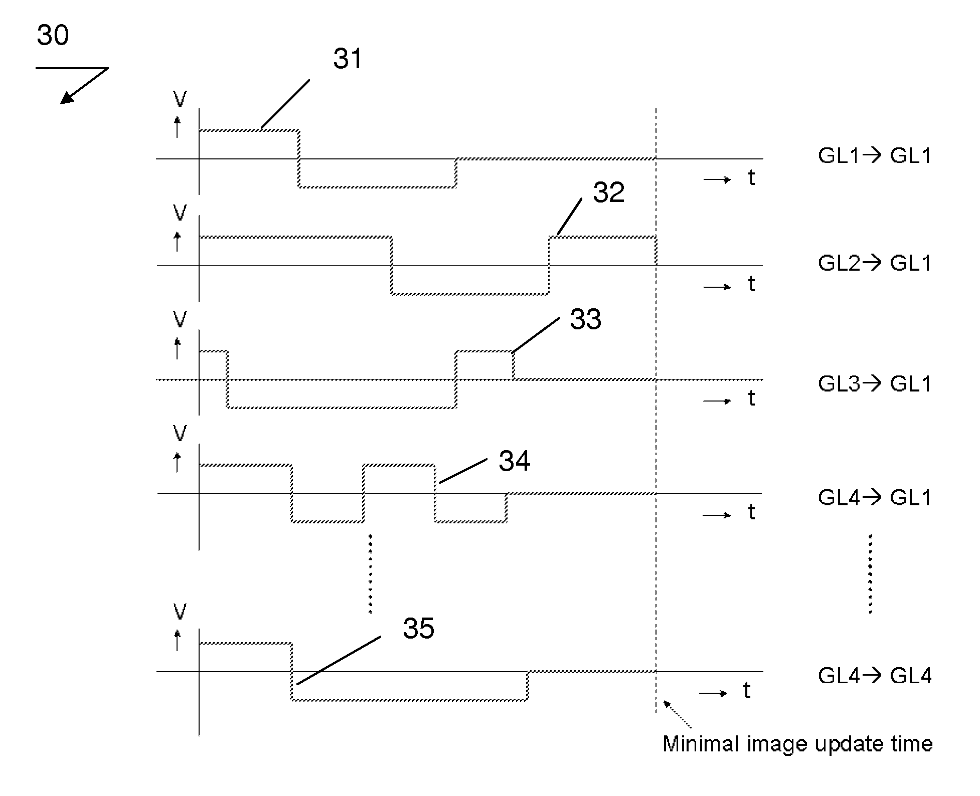
A method of controlling an electronic display having a plurality of pixels settable in a first operating level, a second operating level and an intermediate operating level, the method comprising the step of setting the pixels in a preparatory intermediate operating level immediately prior to setting the pixels in a desired intermediate operating state. At an end of a frame i−1, for example, it is possible to drive a pixel from a level P0 further towards white to reach reflection level Pn or to stop driving it, or to switch a control voltage to an apposite polarity and arrive at a lower level. Levels P1 and P2 present embodiments of preparatory intermediate levels used to drive pixels in accordance with the invention. For example, levels 2, 4, and 6 may be obtained from the preparatory level P1. Levels 3, 5, and 7 may be obtained from the preparatory level P2.

Description

FIELD OF THE INVENTION[0001]The invention relates to a method of controlling an electronic display. More particularly, the invention relates to a method of controlling an electrophoretic display. The invention further relates to an apparatus comprising an electronic display. More particularly, the invention relates to an apparatus comprising a flexible electronic display.BACKGROUND OF THE INVENTION[0002]Electronic displays have a plurality of pixels, which may be settable with a first operating reflection level, a second operating reflection level and an intermediate operating reflection level. Usually, the first level relates to “white”, the second level relates to “black” and the intermediate level relates to “grey”. For example, electronic displays may be based on a per se known electrophoretic material comprising capsules with black and white particles. In order to change image content on an electrophoretic display, new image information is written for a certain amount of time, ...

Claims


Application Information

Patent Timeline
Patent Type & Authority Patents(United States)
IPC IPC(8): G09G5/00
CPCG09G3/344G09G3/2007G09G2310/0251G09G2320/0252
Inventor MARKVOORT, WIEGERVAN VEENENDAAL, ERIK
Owner SAMSUNG ELECTRONICS CO LTD
Learn More