
Installation structure for hydroelectric power generation apparatus

a technology for hydroelectric power generation and installation structure, which is applied in the direction of electric generator control, greenhouse gas reduction, renewable energy generation, etc., can solve the problems of unfavorable hydroelectric power generation apparatus installation, difficult general installation of hydroelectric power generation apparatus, and inability to meet the needs of the environment, so as to achieve the effect of facilitating maintenance and generating a large quantity of power

Active Publication Date: 2013-11-05
JAPAN SYST PLANNING
View PDF19 Cites 0 Cited by
  • Summary
  • Abstract
  • Description
  • Claims
  • Application Information

AI Technical Summary

Benefits of technology

The invention is a power generation apparatus that can be accommodated in a frame and installed in water to efficiently generate power. The frame is designed to accommodate multiple hydroelectric power generation apparatuses, which can be small and closely packed together to generate a large amount of power. The frame is stable and positioned horizontally due to the buoyancy of a buoyancy body. The generators of the power generation apparatuses can be integrated, and the frame has openings for easy maintenance. The technical effects of this invention are a compact, efficient, and stable power generation system that can be installed in water and maintained easily.

Problems solved by technology

Electrical power generation using the energy of flowing water of sea or river generally presents a challenge as to where a hydroelectric power generation apparatus should be installed.
If a hydroelectric power generation apparatus is installed on the surface of water flowing at a high velocity, the water surface on which it is installed may obstruct water transport of ships, etc.
Accordingly, installation of a hydroelectric power generation apparatus is generally difficult.
If a hydroelectric power generation apparatus is installed at the bottom of the water, flow velocity may be low or lots of mud may be present there, which is unfavorable to a hydroelectric power generation apparatus.
It may therefore be difficult for the buoyancy body B to be kept horizontal.
This requires an increase in the size of the buoyancy body B. Additionally, the integration of the generator C and the buoyancy body B contributes to such a problem as the size of a sea-current power generation submarine (i.e., hydroelectric power generation apparatus) increasing and the cost of each hydroelectric power generation apparatus correspondingly increasing excessively.

Method used


Image

  • Installation structure for hydroelectric power generation apparatus
  • Installation structure for hydroelectric power generation apparatus
  • Installation structure for hydroelectric power generation apparatus

Examples


Embodiment Construction

[0032]At least the following details will become apparent from descriptions of this specification and of the accompanying drawings.

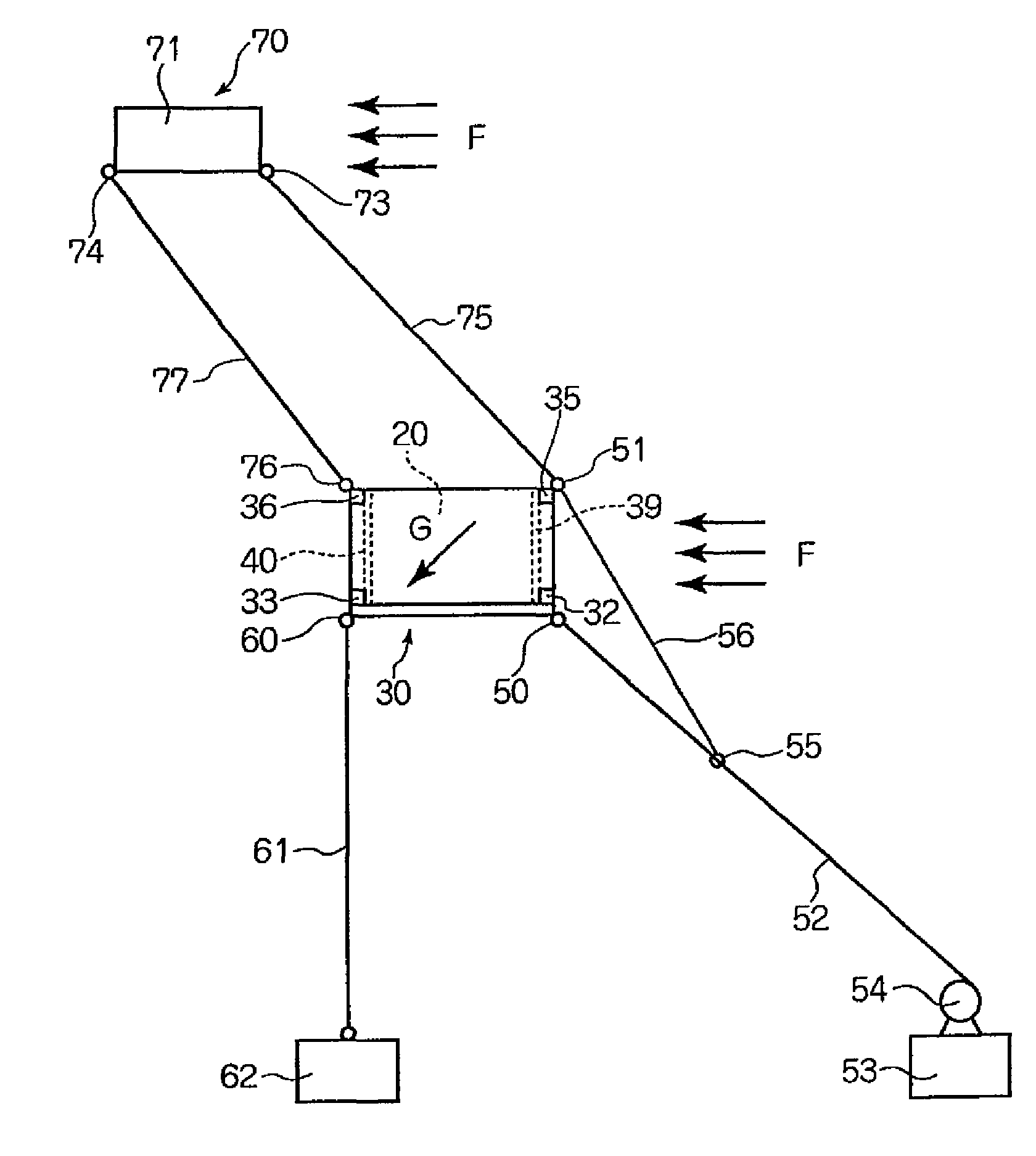
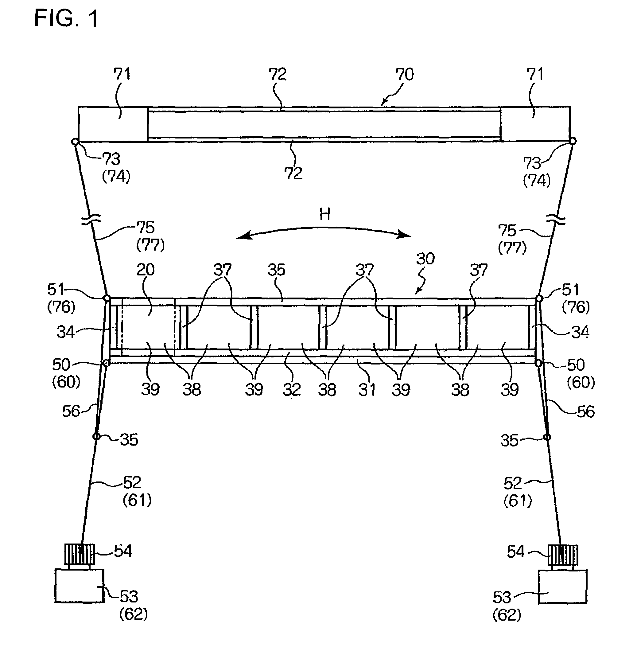
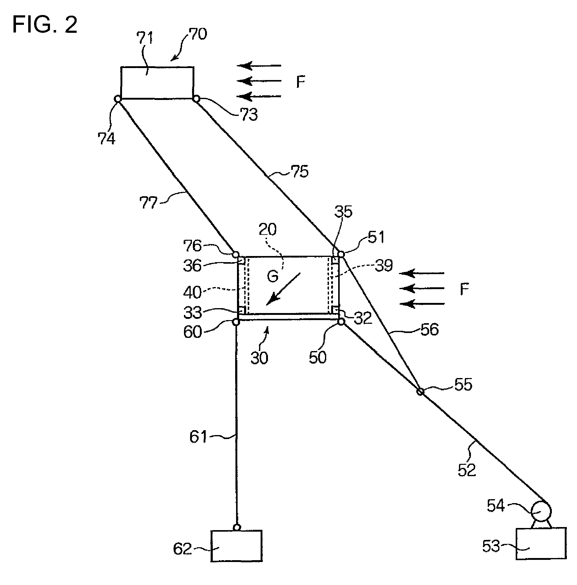
[0033]An installation structure for a hydroelectric power generation apparatus according to an embodiment of the present invention will now be described with reference to FIGS. 1 to 4. The present embodiment uses a power generation apparatus accommodation frame body 30 shown in FIG. 4. A plurality of hydroelectric power generation apparatuses 20 (six hydroelectric power generation apparatuses in this embodiment) can be accommodated in parallel in the power generation apparatus-accommodation frame body 30 from above. Secured on the front and rear portions of a horizontally long bottom plate 31 are lower restricting plates 32 and 33, which restrict the forward and backward directions of the lower part of the hydroelectric power generation apparatus 20. Side plates 34 the four corners of which are notched in a rectangular form are fixed onto each side of th...


PUM


Abstract

An installation structure for a hydroelectric power generation apparatus, includes: a power generation apparatus accommodation frame body in which a plurality of hydroelectric power generation apparatuses are accommodated in parallel; a first wire having one end connected to a lower portion of the power generation apparatus accommodation frame body; an anchor or weight connected with the other end of the first wire; a buoyancy body provided on an upper side of the hydroelectric power generation apparatus accommodation frame body through the second wire, the hydroelectric power generation apparatus accommodation frame body having an upper side opened, and having a dividing plate between both side plates to form a plurality of power generation apparatus accommodation units, each of the plurality of power generation apparatus accommodation units having a running water inlet side window formed at a front portion, and having a running water outlet side window formed at a rear portion.

Description

CROSS REFERENCE TO RELATED APPLICATION[0001]This application claims the benefit of priority to Japanese Patent Application No. 2009-180256, filed Aug. 3, 2009, of which full contents are incorporated herein by reference.BACKGROUND OF THE INVENTION[0002]1. Field of the Invention[0003]The present invention relates to an installation structure for a hydroelectric power generation apparatus that generates hydroelectric power with flowing water of sea or river.[0004]2. Description of the Related Art[0005]Electrical power generation using the energy of flowing water of sea or river generally presents a challenge as to where a hydroelectric power generation apparatus should be installed. If a hydroelectric power generation apparatus is installed on the surface of water flowing at a high velocity, the water surface on which it is installed may obstruct water transport of ships, etc. Accordingly, installation of a hydroelectric power generation apparatus is generally difficult. If a hydroele...

Claims


Application Information

Patent Timeline
Patent Type & Authority Patents(United States)
IPC IPC(8): F03B13/00H02P9/04
CPCF03B17/061F05B2240/133F05B2240/97Y02E10/223Y02E10/28Y02E10/38Y02E10/20Y02E10/30
Inventor KUMANO, KATSUYUKI
Owner JAPAN SYST PLANNING
Learn More