
Selective tunneling based on a client configuration and request

a client configuration and request technology, applied in the field of network communication, can solve problems such as limiting the usefulness of enterprises, increasing risks, and limiting desirable network traffic flows

Inactive Publication Date: 2013-10-29
F5 NETWORKS INC
View PDF28 Cites 17 Cited by
  • Summary
  • Abstract
  • Description
  • Claims
  • Application Information

AI Technical Summary

Benefits of technology

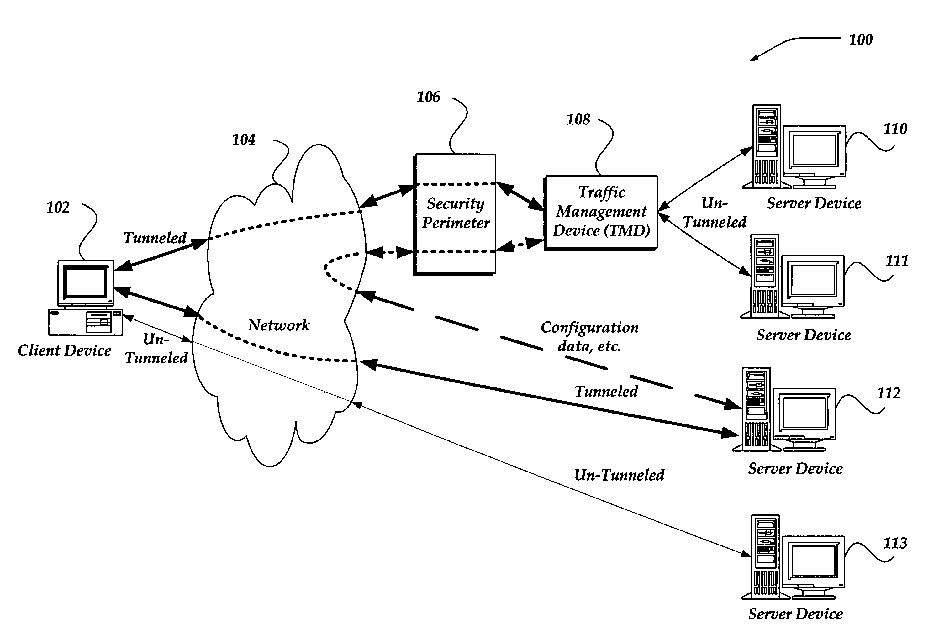
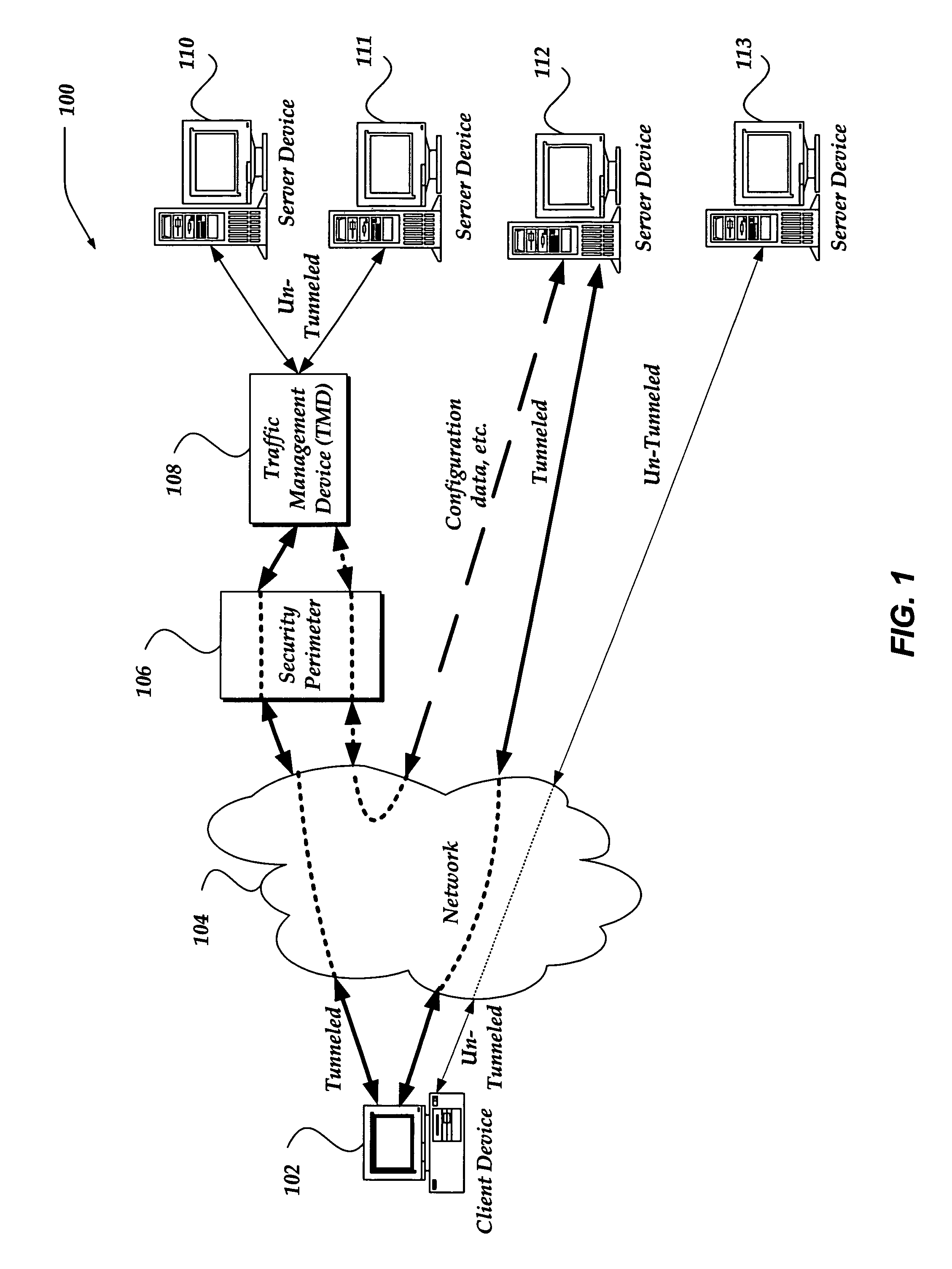
The present invention relates to managing network communications by selectively employing tunneled network connections based on a client configuration and the request of the client. The invention addresses the risks and limitations of traditional solutions such as Virtual Private Networks (VPNs), proxy servers, and reverse proxy servers. The invention provides an improved mechanism to enable communications across a security perimeter by selectively employing tunneled network connections based on the client configuration and the request of the client. The technical effects of the invention include increased security, flexibility, and compliance with legal requirements.

Problems solved by technology

Unfortunately, the risks are growing.
While a security perimeter is designed to restrict improper flow of network traffic between networks, they may also block desirable network traffic flows.
However, each of these solutions also bring with them problems that may limit their usefulness to an enterprise.
For example, in the case of some browsers, some active components embedded within a web page may not properly function through the security perimeter using a proxy server.
Reverse proxy servers may also create complications for communications through the security perimeter.
However, web pages that include client side scripts, active components, or the like, may be virtually impossible to be rewritten and thereby limiting the use of reverse proxy servers.

Method used


Image

  • Selective tunneling based on a client configuration and request
  • Selective tunneling based on a client configuration and request
  • Selective tunneling based on a client configuration and request

Examples


Embodiment Construction

[0016]The present invention now will be described more fully hereinafter with reference to the accompanying drawings, which form a part hereof, and which show, by way of illustration, specific exemplary embodiments by which the invention may be practiced. This invention may, however, be embodied in many different forms and should not be construed as limited to the embodiments set forth herein; rather, these embodiments are provided so that this disclosure will be thorough and complete, and will fully convey the scope of the invention to those skilled in the art. Among other things, the present invention may be embodied as methods or devices. Accordingly, the present invention may take the form of an entirely hardware embodiment, an entirely software embodiment or an embodiment combining software and hardware aspects. The following detailed description is, therefore, not to be taken in a limiting sense.

[0017]Throughout the specification and claims, the following terms take the meanin...


PUM


Abstract

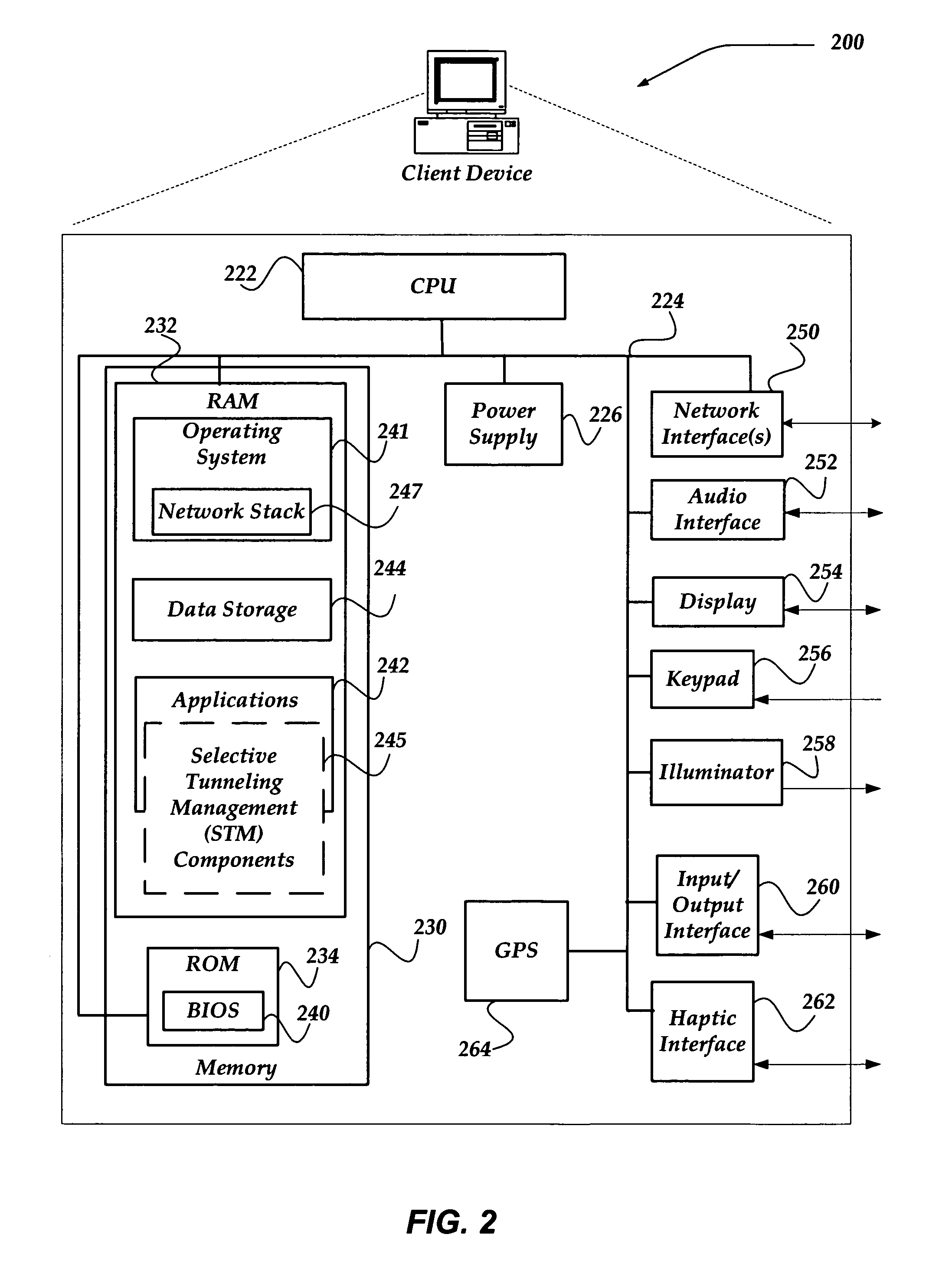
A system, apparatus, and method are directed to network communication over a tunnel by downloading selective tunneling (STM) components into memory of a client device. The STM components selectively employ tunneling to route network traffic to a requested resource. The STM components may include a network API, application, and a tunnel manager that have been modified based in part on a client configuration. As a network request is made it is evaluated against the client configuration. If the connection is to be tunneled, a network tunnel is selectively established. If the client configuration and / or the request indicate that the request is to be un-tunneled, an un-tunneled network connection may instead be established. The client configuration may also indicate that the client device is to be redirected to enable remediation. When the application component is closed, or otherwise terminated, the client's memory may be purged of the loaded STM components.

Description

CROSS-REFERENCE TO RELATED APPLICATIONS[0001]The present application claims benefit of provisional application Ser. No. 60 / 778,357 entitled “Selective Tunneling Based On A Client Configuration And Request,” filed on Mar. 2, 2006, the benefit of the earlier filing date of which is hereby claimed under 35 U.S.C. §119 (e) and 37C.F.R. §1.78, and which is further incorporated by reference.BACKGROUND OF THE INVENTION[0002]This invention relates generally to network communications, and more particularly but not exclusively, to managing network communications by selectively employing tunneled network connections based, in part, on a client configuration and the request.[0003]Many of today's enterprises regularly use the Internet to remotely connect employees, business partners, and, even customers to hosted resources. The benefits are significant, but not without risk. Unfortunately, the risks are growing.[0004]In response to the growing risks of attacks, potentials for legal suits, federa...

Claims


Application Information

Patent Timeline
Patent Type & Authority Patents(United States)
IPC IPC(8): G06F15/177H04M3/00G06F21/00G06F15/16
CPCH04L63/0272H04L63/105H04L63/168
Inventor SHIGAPOV, ANDREY
Owner F5 NETWORKS INC
Learn More