
Electronic timepiece with internal antenna

an electronic timepiece and antenna technology, applied in the field of electronic timepieces with internal antennas, can solve the problems of difficult balance between reception performance and small wristwatch size, and achieve the effect of high reception performan

Active Publication Date: 2013-10-29
SEIKO EPSON CORP
View PDF10 Cites 24 Cited by
  • Summary
  • Abstract
  • Description
  • Claims
  • Application Information

AI Technical Summary

Benefits of technology

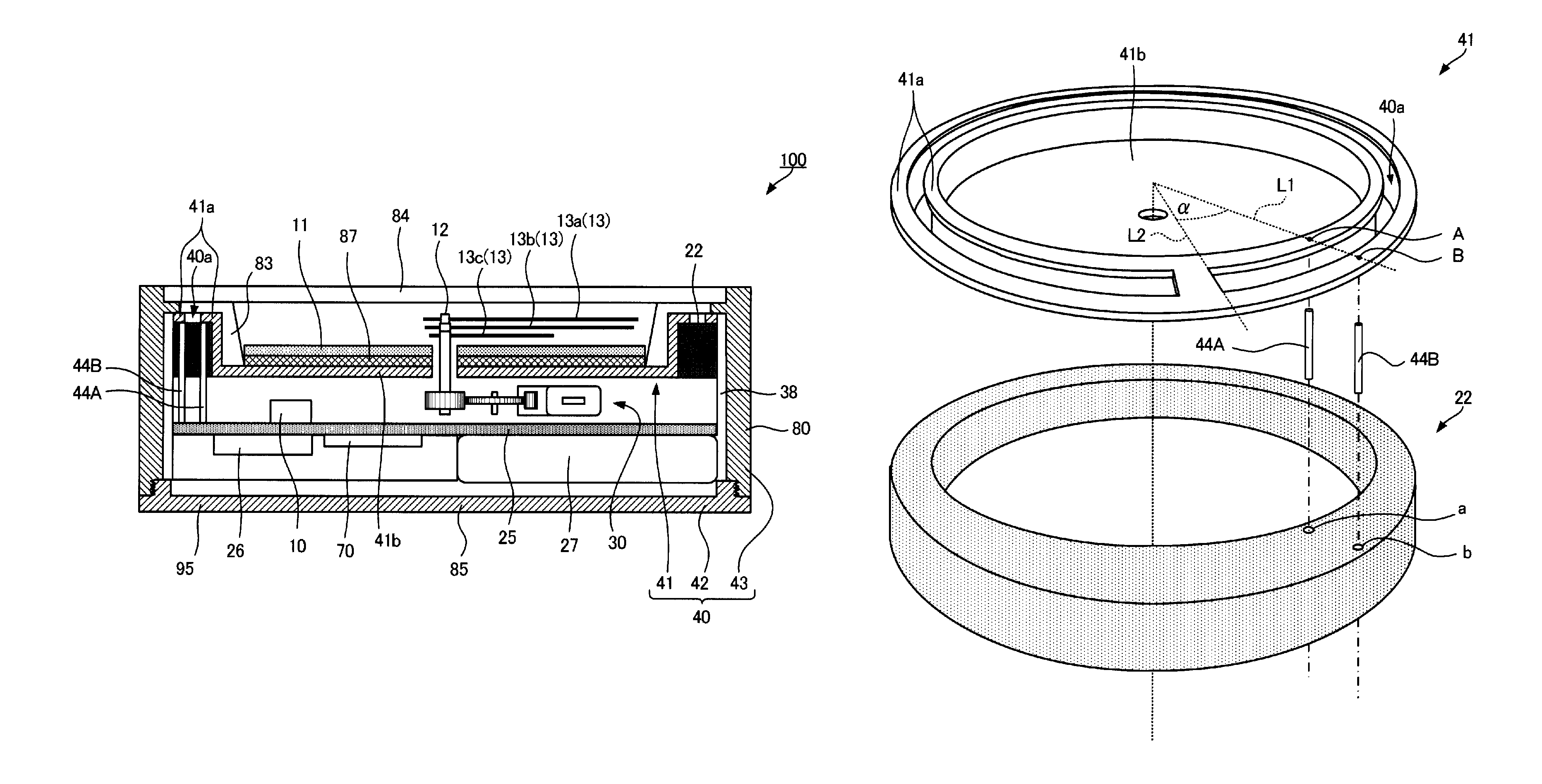
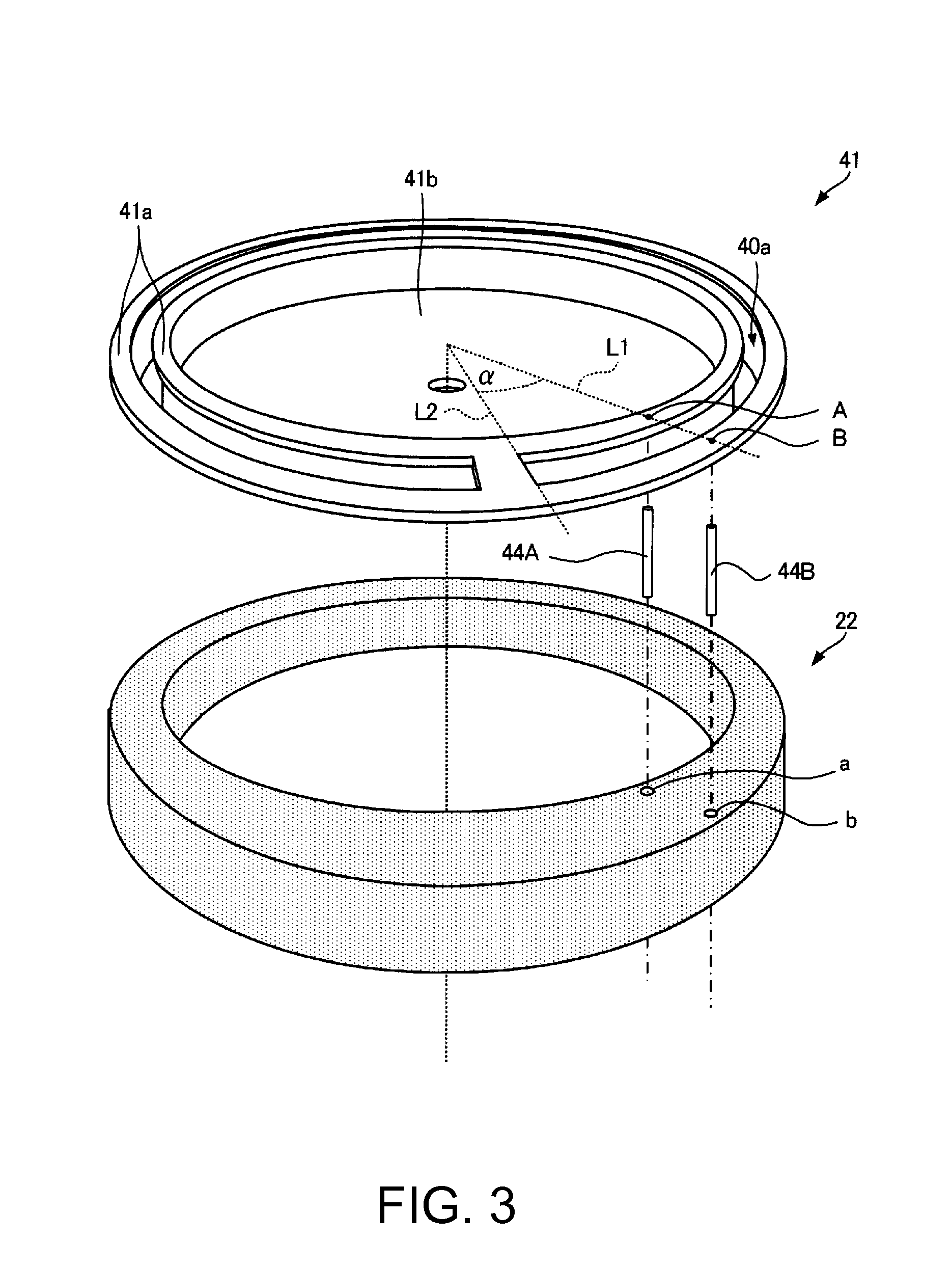
The present invention solves the problem of maintaining high reception performance of circularly polarized waves even in a metal case for a small electronic timepiece with an internal antenna. The antenna functions as a slot antenna, which is not affected by a metal case. The slot extends circumferentially to the side part, allowing for reception of satellite signals and other circularly polarized waves. The size of the antenna can be increased while saving space by using a dielectric covering the slot. The drive mechanism is housed inside the antenna. The bottom part does not need to be separately provided, reducing size and weight. The dial is not positioned between the slot and the crystal, ensuring good reception performance. The metal part of the external case is part of the antenna, making it a more compact size and lighter weight. Opening a hole in the center of the top part does not detrimentally affect reception performance.

Problems solved by technology

While the electronic timepiece with an internal antenna described in JP-A-2000-59241 has a metal case, balancing maintaining reception performance with a small wristwatch size is difficult because the antenna electrode and the ground plane (case member) must be sufficiently separated in order to ensure sufficiently high reception performance.

Method used


Image

  • Electronic timepiece with internal antenna
  • Electronic timepiece with internal antenna
  • Electronic timepiece with internal antenna

Examples


embodiment 1

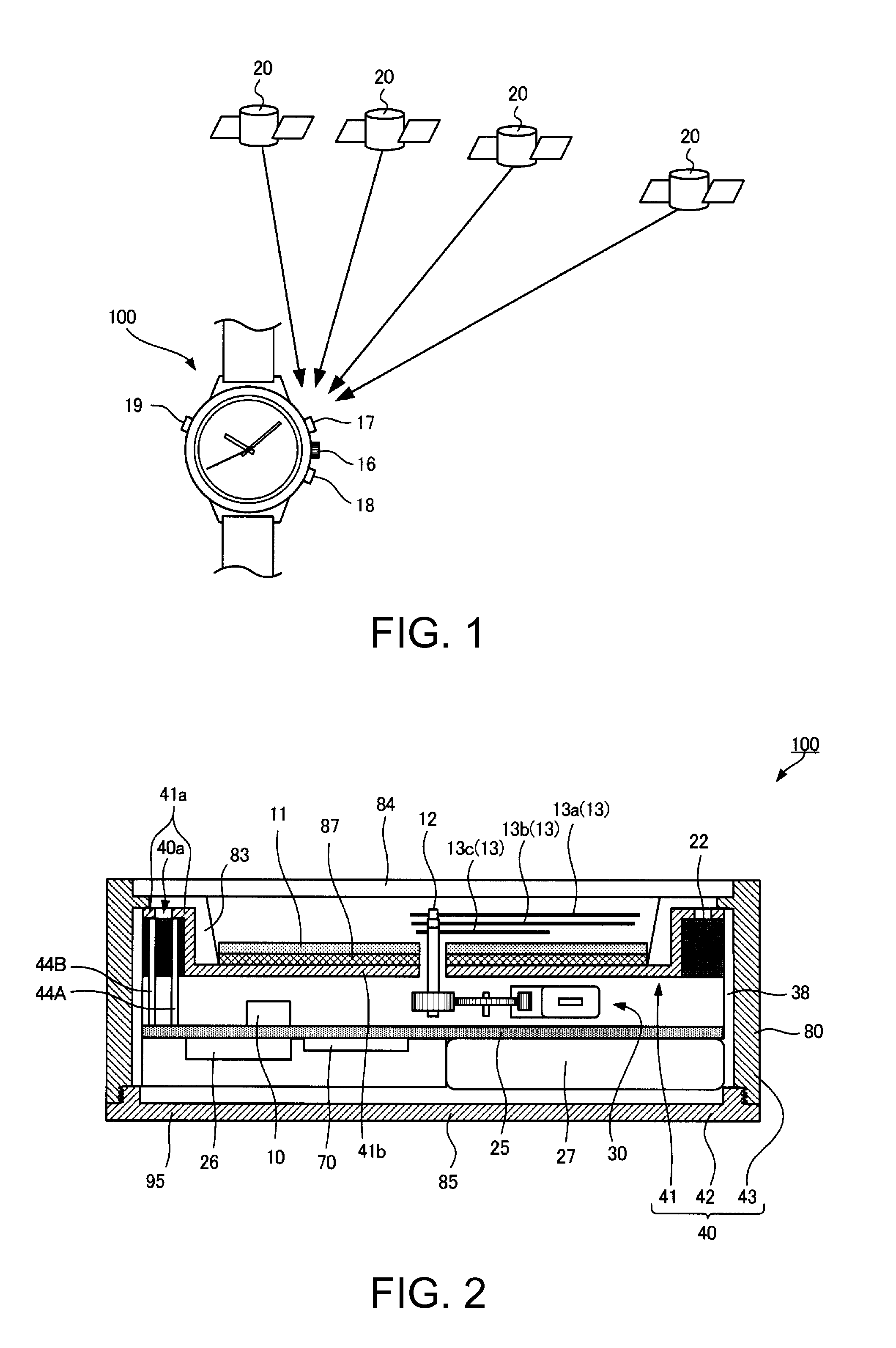
[0049]FIG. 1 shows the general configuration of a GPS system including an electronic timepiece with internal antenna 100 (electronic timepiece 100) according to a first embodiment of the invention. This electronic timepiece 100 is a wristwatch that receives signals (radio signals) from GPS satellites 20 and adjusts the internal time, and displays the time on the surface (side) (referred to below as the “face”) on the opposite side as the surface (referred to below as the “back”) that contacts the wrist.

[0050]A GPS satellite 20 is a positioning information satellite that orbits the Earth on a fixed orbit, and transmits navigation messages superimposed on a 1.57542 GHz RF signal (L1 signal). The 1.57542 GHz signal carrying a superimposed navigation message is referred to herein as simply a “satellite signal.” These satellite signals are right-handed circularly polarized waves.

[0051]There are currently approximately 31 GPS satellites 20 in orbit (only 4 of the 31 satellites are shown i...

embodiment 2

[0108]FIG. 6 is a partial section view of an electronic timepiece with internal antenna 200 (electronic timepiece 200) according to a second embodiment of the invention, and FIG. 7 is an exploded perspective view of part of the electronic timepiece 200. The antenna 45 used in this electronic timepiece 200 differs from the antenna 40 in the foregoing electronic timepiece 100. This antenna 45 is made of metal similarly to antenna 40, but differs from antenna 40 by using antenna electrode 46 instead of antenna electrode 41.

[0109]This antenna electrode 46 has an annular slot part 46a instead of slot part 41a, and a round center part 46b instead of center part 41b. The slot part 46a and center part 46b are discrete parts. The slot part 46a is an electrode pattern formed by electroless plating of a metal such as copper, nickel, or gold on part of the dielectric 22. The center part 41b is a stainless steel plate, and has a hole formed in the center through which the center shaft 12 passes....

embodiment 3

[0114]FIG. 8 is a partial section view of an electronic timepiece with internal antenna 300 (electronic timepiece 300) according to a third embodiment of the invention, and FIG. 9 is an exploded perspective view of part of the electronic timepiece 300. This electronic timepiece 300 differs from the electronic timepiece 100 described above by using antenna 49 and external case (metal part) 90 instead of antenna 40 and case 80.

[0115]This antenna 49 differs from antenna 40 by having antenna electrode 47 and side part 48 instead of antenna electrode 41 and side part 43. While the case 80 functions as the side part 43 in electronic timepiece 100 above, case 90 functions as the side part 48 in this embodiment. This case 90 differs from case 80 only by the inside shape. The antenna electrode 47 has a slot part 47a corresponding to slot part 41a, and a center part 47b corresponding to center part 41b. The slot part 47a has a C-shaped slot 40a identical to slot part 41a, but differs from slo...


PUM


Abstract

An electronic timepiece with internal antenna maintains sufficiently high reception performance of circularly polarized waves even when having a metal external case. The timepiece has a cylindrical case; a crystal that covers the opening on the face side of the case; a drive mechanism that arranged inside the case; a metal antenna; and a dielectric. The antenna houses the drive mechanism and has a cylindrical side part, a bottom part that covers the opening on the back side of the side part, and an antenna electrode that contacts the inside of the side part. The back cover covers the back side of the case and is also the bottom part. The dielectric extends circumferentially to the side part, and contacts the antenna electrode in the face-back cover direction. A slot extending circumferentially is formed in the antenna electrode. Part or all of the slot is covered by the dielectric.

Description

CROSS-REFERENCE TO RELATED APPLICATIONS[0001]Priority is claimed under 35 U.S.C. §119 to Japanese Application Nos. 2010-253429, filed on Nov. 12, 2010 and 2011-144253, filed on Jun. 29, 2011, which are hereby incorporated by reference in their entirety.BACKGROUND[0002]1. Technical Field[0003]The present invention relates to an electronic timepiece with an internal antenna.[0004]2. Related Art[0005]Japanese Unexamined Patent Appl. Pub. JP-A-2000-59241 teaches an electronic timepiece with internal antenna that has a ring antenna (dipole antenna) that uses a metal case member as a ground plane. Because the ground plane operates as a reflector in this ring antenna, the ground plane must be sufficiently separated from the antenna electrode on a dielectric. Japanese Unexamined Patent Appl. Pub. JP-A-H07-193416 teaches an electronic timepiece with an internal antenna that houses a slot antenna inside the external case. A slot antenna is an antenna with a slot (slit) in a metal plate.[0006]...

Claims


Application Information

Patent Timeline
Patent Type & Authority Patents(United States)
IPC IPC(8): G04C11/00H01Q13/10G04G21/04G04R20/00G04R60/06G04R60/12
CPCG04C10/02G04R60/12H01Q1/273H01Q13/10G04R60/06G04R60/10H01Q9/0421
Inventor FUJISAWA, TERUHIKO
Owner SEIKO EPSON CORP
Learn More