Ultrasonic image processing apparatus and ultrasonic image processing method
a processing apparatus and ultrasonic technology, applied in the field of ultrasonic image processing apparatus, can solve the problems of reducing the display size per image, difficult for an observer to simultaneously grasp all images, and inability to implement chronological observation of locally the same region, etc., to achieve accurate and rapid acquisition of three-dimensional motion information.
- Summary
- Abstract
- Description
- Claims
- Application Information
AI Technical Summary
Benefits of technology
Problems solved by technology
Method used
Image
Examples
first embodiment
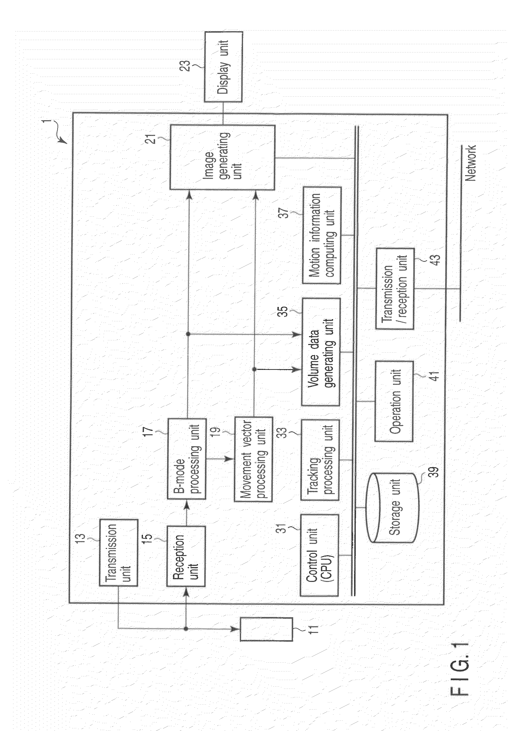
[0038]FIG. 1 is a block diagram showing the arrangement of an ultrasonic diagnosis apparatus 1 according to the first embodiment. The ultrasonic diagnosis apparatus 1 comprises an ultrasonic probe 11, a transmission unit 13, a reception unit 15, a B-mode processing unit 17, a movement vector processing unit 19, an image generating unit 21, a display unit 23, a control unit (CPU) 31, a tracking processing unit 33, a volume data generating unit 35, a motion information computing unit 37, a storage unit 39, an operation unit 41, and a transmission / reception unit 43. Note that when the present invention is applied to an ultrasonic image processing apparatus, the constituent elements of the apparatus are those enclosed by the dotted line in FIG. 1.
[0039]The ultrasonic probe 11 includes a plurality of piezoelectric transducers which generate ultrasonic waves on the basis of driving signals from the transmission unit 12 and convert reflected waves from an object to be examined into electri...
example 1
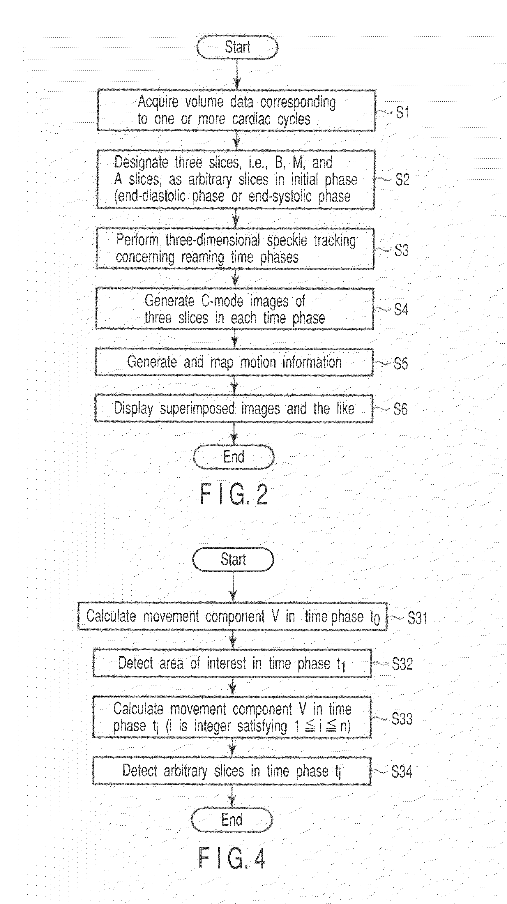
[0061]The tracking method according to this example obtains a movement component V by projecting movement vectors at the respective positions of tissues existing on the respective slices in the normal direction and averaging the vectors, and tracking an arbitrary slice in each time phase by using the movement component.
[0062]FIG. 4 is a flowchart showing a sequence of arbitrary slice tracking processing in step S3. As shown in FIG. 4, first of all, movement component V=Vz,mean(t0) in the initial time phase t0 is calculated by averaging only normal-direction components (projection components in the normal direction shown by “z” in FIG. 4) of movement vectors of the respective tissues (i.e., the positions of tissues contained in the respective surfaces) on the B, M, and A surfaces set for the volume data of the initial time phase (step S31).
[0063]The B, M, and A surfaces set in the initial time phase are translated by movement component V=Vz,mean(t0) along the normal direction, and ca...
example 2
[0068]The tracking method according to this example obtains the movement component V by averaging movement vectors at the respective positions of tissues existing in set arbitrary slices (without projection in the normal direction) and tracks arbitrary slices in each time phase by using the obtained component.
[0069]Referring to FIG. 4, first of all, movement component V=Vmean(t0) is calculated by averaging the movement vectors of the respective myocardials (i.e., the respective positions on tissues included in the respective surfaces) in the B, M, and A surfaces set for the volume data of the initial time phase (step S31).
[0070]The B, M, and A surfaces set in the initial time phase are translated by movement component V=Vmean(t0) to set the B, M, and A surfaces in the time phase t1 (step S32).
[0071]Movement component V=Vmean(ti) in the time phase ti (i is an integer satisfying 2≦i≦n) is calculated by averaging the movement vectors of the respective myocardials on the B, M, and A sur...
PUM
 Abstract
Description
Claims
Application Information
 - R&D
- Intellectual Property
- Life Sciences
- Materials
- Tech Scout
- Unparalleled Data Quality
- Higher Quality Content
- 60% Fewer Hallucinations
Browse by: Latest US Patents, China's latest patents, Technical Efficacy Thesaurus, Application Domain, Technology Topic, Popular Technical Reports.
© 2025 PatSnap. All rights reserved.Legal|Privacy policy|Modern Slavery Act Transparency Statement|Sitemap|About US| Contact US: help@patsnap.com


