Digital image sender, digital image receiver, digital image transmission system and digital image transmission method

a digital image and sender technology, applied in the field of digital image sender, digital image receiver, digital image transmission system and digital image transmission method, can solve the problems of composite cable, cumbersome installation and use of composite cable, large diametrical size of optical fiber and metal wire, etc., to achieve the effect of superior flexibility, and reducing the number of transmission paths

Inactive Publication Date: 2013-10-15
SONY CORP
View PDF12 Cites 11 Cited by
  • Summary
  • Abstract
  • Description
  • Claims
  • Application Information

AI Technical Summary

Benefits of technology

[0020]However, a demand not only for a higher resolution of an image signal but also for a wider color bandwidth and a higher frame rate has been and is increasing in recent years. Therefore, there is the possibility that the transmission rate of a digital image signal may rise to a band of 10 Gbps or more. In this instance, in order to transmit a high speed serial image signal, also various devices such as multiplexers and demultiplexers must cope with the high rate. Therefore, there is the possibility that the entire apparatus may require a higher cost.
[0042]With the digital image transmission system and the digital image transmission method, since it has the configuration described above, a reference clock signal and parallel control signals can be transmitted as a single superposition signal in the form of an optical signal. Consequently, the band utilization efficiency can be raised, and the number of transmission paths, electro-optical converters and opto-electrical converters can be suppressed to the minimum. Besides, since all signals are transmitted by optical transmission, the cable for the transmission can be formed with a reduced diameter when compared with an alternative cable for which metal wires are used, and besides is free from the problem of the EMI.

Problems solved by technology

(1) According to the digital video signal interface module disclosed in Patent Document 1, a composite cable wherein, for example, four optical fibers and five metal wires are bundled is used for the transmission.
However, such a composite cable of optical fibers and metal wires as just described has a generally large diametrical size and lacks in flexibility.
Accordingly, the composite cable is cumbersome in installation and use and usually needs a high cost.

Method used


Image

  • Digital image sender, digital image receiver, digital image transmission system and digital image transmission method
  • Digital image sender, digital image receiver, digital image transmission system and digital image transmission method
  • Digital image sender, digital image receiver, digital image transmission system and digital image transmission method

Examples


embodiment 1

[Embodiment 1]

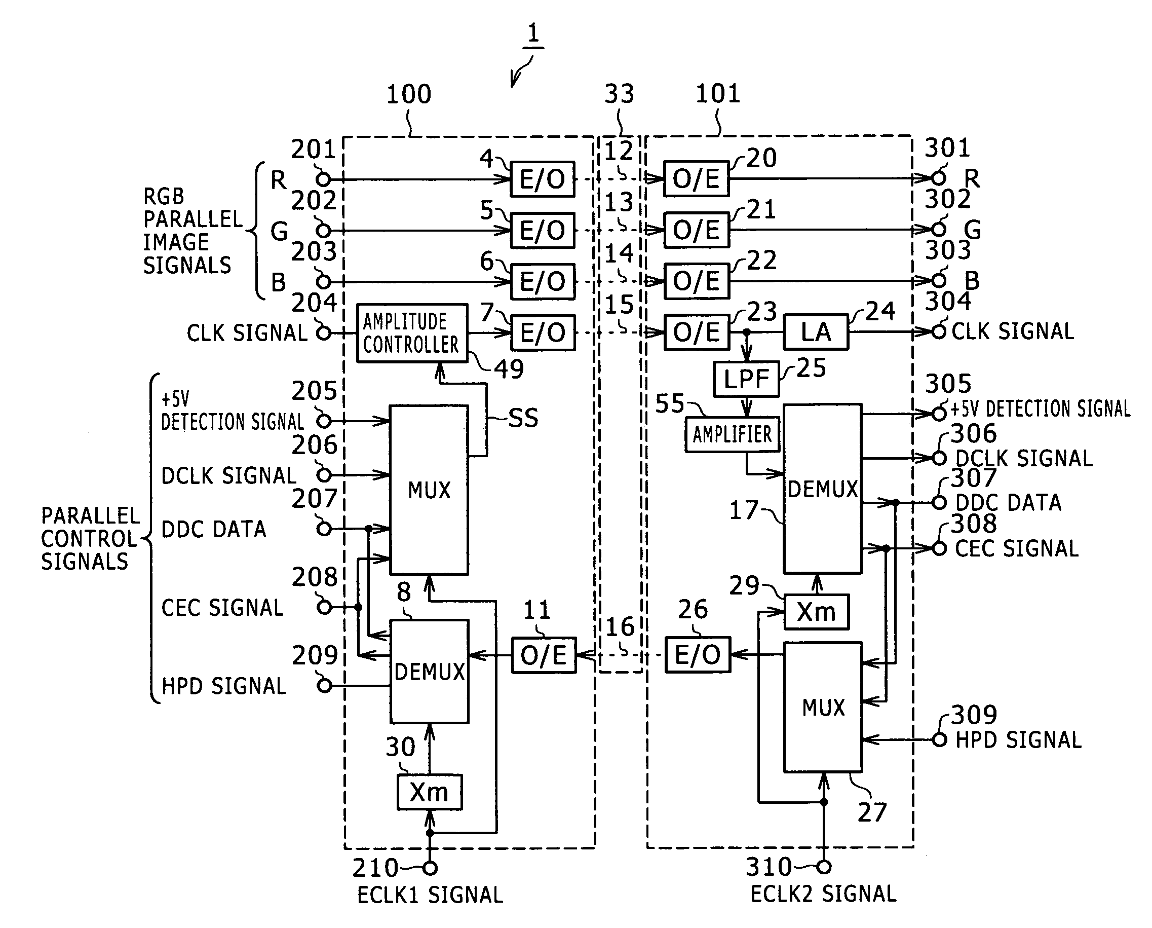
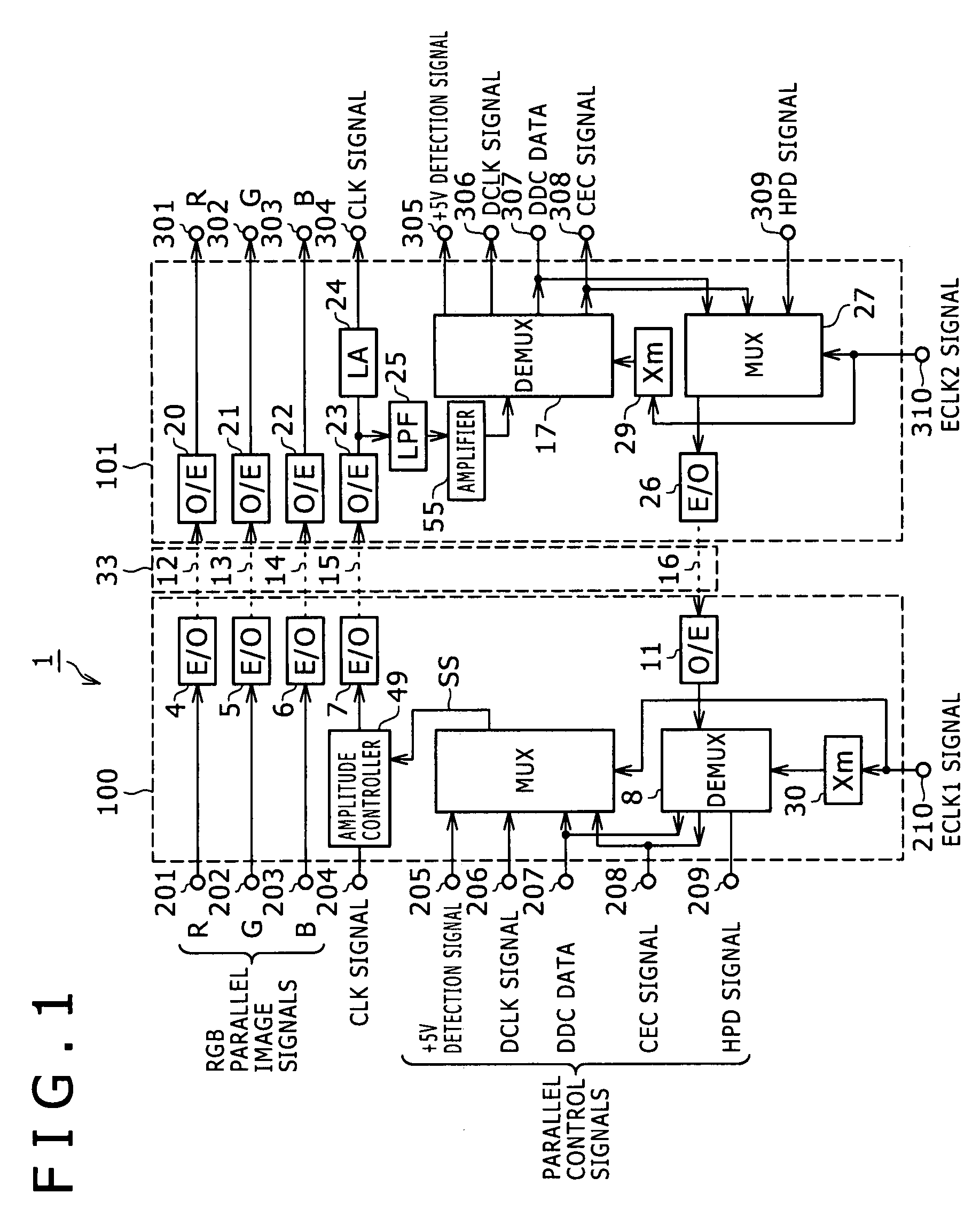
[0054]FIG. 1 shows an example of a configuration of a digital image transmission system to which the present invention is applied. Referring to FIG. 1, the digital image transmission system 1 shown forwardly transmits a digital image signal including RGB parallel image signals, a reference clock signal and parallel control signals from a digital image outputting apparatus such as a computer or a video image reproduction apparatus to a digital image inputting apparatus such as a liquid crystal monitor or a projector. The digital image transmission system 1 further has a function of backwardly transmitting parallel control signals from the digital image inputting apparatus to the digital image outputting apparatus.

[0055]The digital image transmission system 1 includes an image sender 100 for transmitting a digital image signal, and an image receiver 101 for receiving the digital image signal from the image sender 100. An optical fiber cable 33 including five optical fibe...

embodiment 2

[Embodiment 2]

[0106]FIG. 7 shows an example of a configuration of another digital image transmission system to which the present invention is applied. Referring to FIG. 7, the digital image transmission system 2 shown includes an image sender 102 for transmitting a digital image signal and an image receiver 103. The digital image transmission system 2 further includes an optical fiber cable 33 including five optical fibers 12 to 16 as a transmission path between the image sender 102 and the image receiver 103.

[0107]The image sender 102 is similar to but different from the image sender 100 of the digital image transmission system 1 described hereinabove in that it does not include the amplitude controller 49 of the image sender 100 but includes an n-fold multiplier 70. Meanwhile, the image receiver 103 is similar to but different from the image receiver 101 of the digital image transmission system 1 described hereinabove in that it includes a high-pass filter (HPF) circuit 71 in plac...


PUM


Abstract

Herein disclosed a digital image sender for transmitting a digital image signal including image signals for color image reproduction, a reference clock signal and parallel control signals, including: a parallel / serial converter configured to convert the parallel control signals into a serial control signal by time division multiplexing; a superposition element configured to superpose the serial control signal obtained by the conversion by said parallel / serial converter on the reference clock signal and output a resulting superposition signal; and an electro-optic converter configured to convert the superposition signal outputted from said superposition element from an electric signal into an optical signal.

Description

CROSS REFERENCES TO RELATED APPLICATIONS[0001]The present invention contains subject matter related to Japanese Patent Application JP 2006-127811 filed with the Japan Patent Office on May 1, 2006, the entire contents of which being incorporated herein by reference.BACKGROUND OF THE INVENTION[0002]1. Field of the Invention[0003]This invention relates to a digital image sender, a digital image receiver, a digital image transmission system and a digital image transmission method which allow long-haul transmission of a digital image signal.[0004]2. Description of the Related Art[0005]In recent years, the DVI (Digital Visual Interface) standards used principally in computers and the HDMI (High Definition Multimedia Interface) standards which define additional functions for home appliances based on the DVI standards have been proposed for the transmission of a digital image signal.[0006]Digital transmission based on the interface standards mentioned decreases fluctuation and blurring of a...

Claims


Application Information

Patent Timeline
Patent Type & Authority Patents(United States)
IPC IPC(8): H04N5/38H04J3/04H04N5/44G06F13/00H04B10/00G09G3/20G09G5/00H04B10/07H04B10/556H04J14/08H04N7/173H04N21/238H04N21/61H04N21/6543
CPCG09G5/006G09G2330/06
Inventor HONGO, KAZUHIROYOSHIFUJI, KAZUNARI
Owner SONY CORP
Why Eureka
Try Eureka