Composite fabrication apparatus

a fabrication apparatus and composite technology, applied in the direction of manufacturing tools, applications, shaping tools, etc., can solve the problems of not allowing for the optimal controlled cool-down, current processing techniques may have limitations in forming desired components, and not optimizing the performance of current resin systems

Active Publication Date: 2013-10-15
THE BOEING CO
View PDF120 Cites 10 Cited by
  • Summary
  • Abstract
  • Description
  • Claims
  • Application Information

AI Technical Summary

Problems solved by technology

Current processing techniques include the use of heated dies, and therefore, may not allow for the optimum controlled cool-down which may be required for optimum fabrication.
Furthermore, current processing techniques may have limitations in forming the desired components since such techniques have limitations in the capability to hold the dimensions of the component accurately or maintain the composite in a fully consolidated state and may not optimize performance of the current resin systems.

Method used


Image

  • Composite fabrication apparatus
  • Composite fabrication apparatus
  • Composite fabrication apparatus

Examples


Embodiment Construction

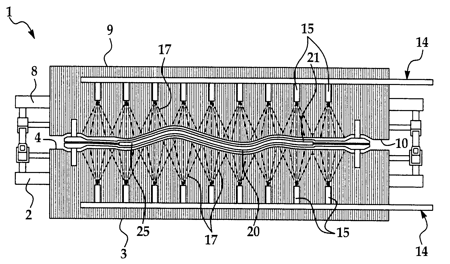
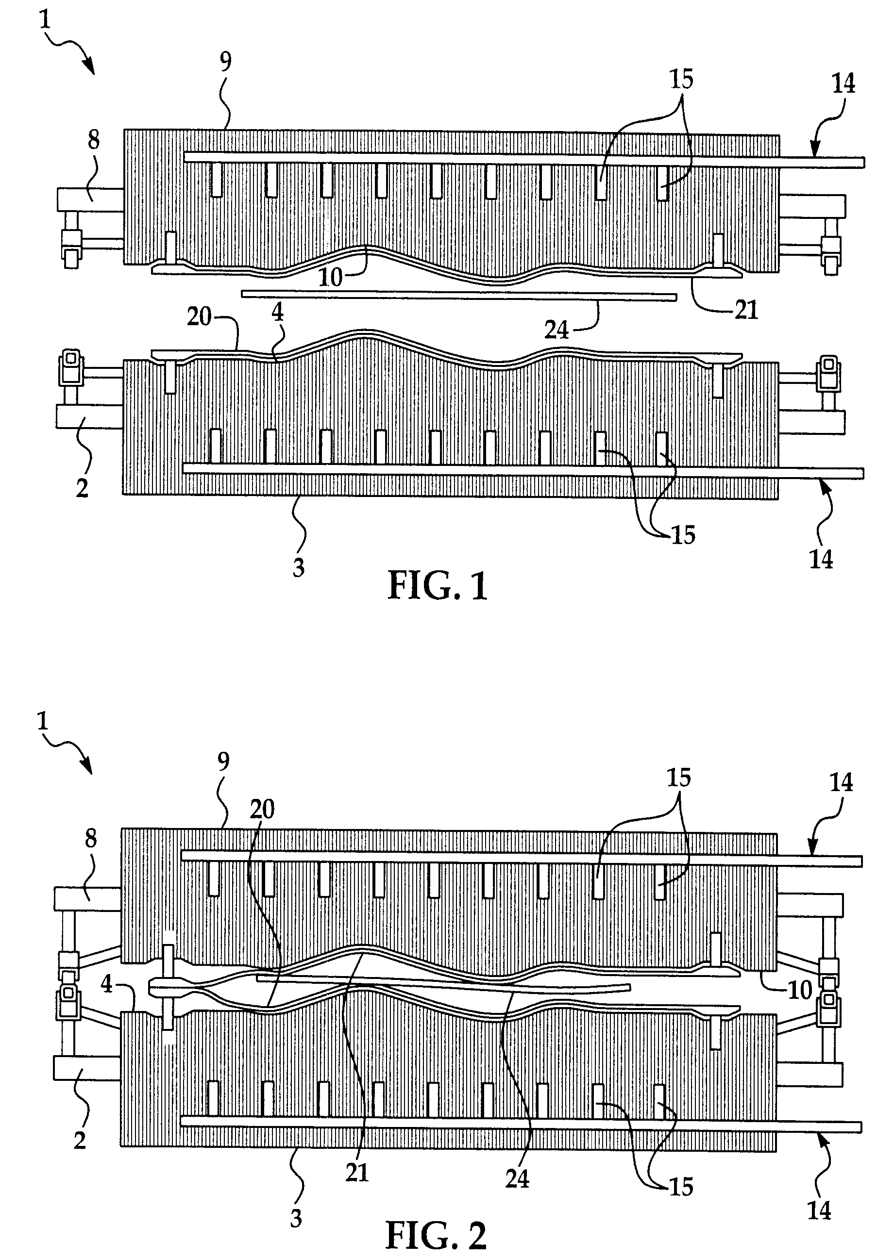
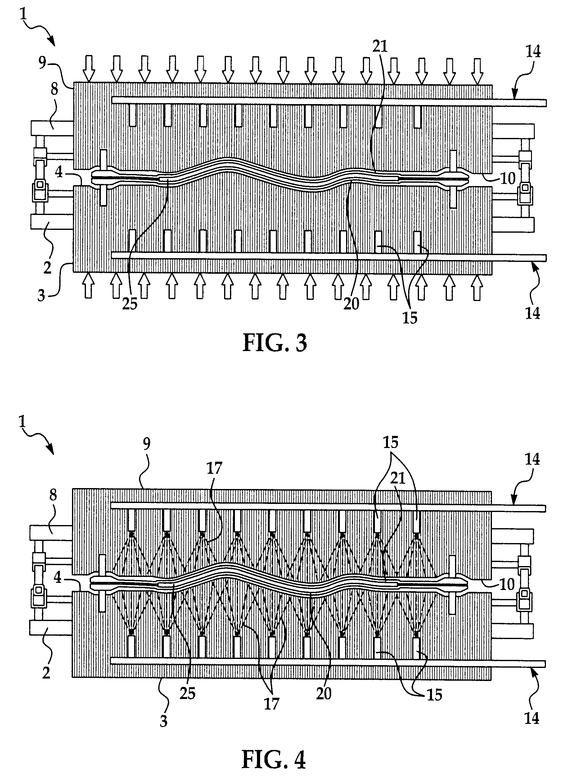
[0020]Referring initially to FIGS. 1-7 of the drawings, a stacked tooling apparatus which is suitable for implementation of the composite fabrication method is generally indicated by reference numeral 1. The stacked tooling apparatus 1 may include a first die frame 2 and a second die frame 8. A first tooling die 3 may be provided on the first die frame 2, and a second tooling die 9 may be provided on the second die frame 8. The first tooling die 3 and the second tooling die 9 may be hydraulically-actuated to facilitate movement of the first tooling die 3 and the second tooling die 9 toward and away from each other. The first tooling die 3 may have a first contoured die surface 4, whereas the second tooling die 9 may have a second contoured die surface 10 which is complementary to the first contoured die surface 4 of the first tooling die 3.

[0021]As shown in FIG. 6, multiple induction coils 26 may extend through each of the first tooling die 3 (and the second tooling die 9, not shown...


PUM

PropertyMeasurementUnit
thicknessaaaaaaaaaa
thermal expansionaaaaaaaaaa
electrically insulatingaaaaaaaaaa

Abstract

A composite fabrication apparatus which may include a first tooling die and a second tooling die movable with respect to each other; a thermal control system having induction coils disposed in thermal contact with the first tooling die and the second tooling die; a first die susceptor provided on the first tooling die and a second die susceptor provided on the second tooling die and connected to the induction coils; and a cooling system disposed in thermal contact with the first tooling die and the second tooling die. A composite fabrication method is also disclosed.

Description

[0001]This application is a divisional application of U.S. application Ser. No. 11 / 854,733, filed Sep. 13, 2007, now issued as U.S. Pat. No. 8,017,059 issued on Sep. 19, 2011; and this application claims priority therefrom.BACKGROUND INFORMATION[0002]1. Field[0003]The disclosure relates to composite fabrication apparatus and methods. More particularly, the disclosure relates to a composite fabrication apparatus and method which optimizes performance of a composite material fabricated according to the method.[0004]2. Background[0005]Processing techniques and facilities which enable widespread use of molded thermoplastic composite components at production rates and production costs and that allow significant weight savings scenarios may be desirable in some applications. The capability to rapidly heat, consolidate and cool in a controlled manner may be required for high production rates of composite components. Current processing techniques include the use of heated dies, and therefor...

Claims


Application Information

Patent Timeline
Patent Type & Authority Patents(United States)
IPC IPC(8): B29C35/00B21D37/16
CPCB21D37/16B29C33/06B29C33/302B29C35/0805B29C35/16B29C43/36B29C43/52B29C70/46B29C70/54B29C33/04B29C33/046B29C33/08B29C2035/0811B29C2035/1616B29C2035/1658B29C2035/1691B29K2105/0854
Inventor MATSEN, MARC R.PETERSON, KIM E.DYKSTRA, WILLIAM
Owner THE BOEING CO
Why Eureka
Try Eureka