
Generating and debugging timing accurate simulations in a graphical specification and constraint language

a constraint language and simulation technology, applied in the field of programming, can solve the problems of manual analysis and testing, application footprint constraints, and applications to be implemented in programmable hardware, and achieve the effect of facilitating the design and development of programs

Active Publication Date: 2013-10-08
NATIONAL INSTRUMENTS
View PDF12 Cites 24 Cited by
  • Summary
  • Abstract
  • Description
  • Claims
  • Application Information

AI Technical Summary

Benefits of technology

The patent describes a system and method for creating and analyzing programs. The system allows users to create programs using a graphical program development environment, which includes a language for specifying and declaring constraints on the program. The system then automatically generates a program that meets the specified model of computation and constraints. The program can be used to configure a programmable hardware element to perform the functions of the program. The system also allows users to analyze the performance and resource utilization of the program, and change the model of computation to improve performance. Overall, the system simplifies the process of creating and analyzing programs, making it easier for R&D personnel to design and develop new programs.

Problems solved by technology

Moreover, such applications may be subject to various constraints, e.g., with respect to timing, resource usage, throughput, etc.
For example, applications to be implemented in programmable hardware, such as a field programmable gate array (FPGA) may be subject to constraints regarding the application's footprint, i.e., area used, on the FPGA.
Prior art techniques for specifying and implementing such applications have typically required significant manual analysis and testing, which is difficult, tedious, and error prone.

Method used


Image

  • Generating and debugging timing accurate simulations in a graphical specification and constraint language
  • Generating and debugging timing accurate simulations in a graphical specification and constraint language
  • Generating and debugging timing accurate simulations in a graphical specification and constraint language

Examples


Embodiment Construction

Incorporation by Reference

[0056]The following references are hereby incorporated by reference in their entirety as though fully and completely set forth herein:[0057]U.S. Provisional Application Ser. No. 61 / 369,624, titled “Specifying and Implementing Applications Via a Disciplined Design Methodology”, filed on Jul. 30, 2010.[0058]U.S. Pat. No. 4,914,568 titled “Graphical System for Modeling a Process and Associated Method,” issued on Apr. 3, 1990.[0059]U.S. Pat. No. 5,481,741 titled “Method and Apparatus for Providing Attribute Nodes in a Graphical Data Flow Environment”.[0060]U.S. Pat. No. 6,173,438 titled “Embedded Graphical Programming System” filed Aug. 18, 1997.[0061]U.S. Pat. No. 6,219,628 titled “System and Method for Configuring an Instrument to Perform Measurement Functions Utilizing Conversion of Graphical Programs into Hardware Implementations,” filed Aug. 18, 1997.[0062]U.S. Pat. No. 7,210,117 titled “System and Method for Programmatically Generating a Graphical Program...


PUM


Abstract

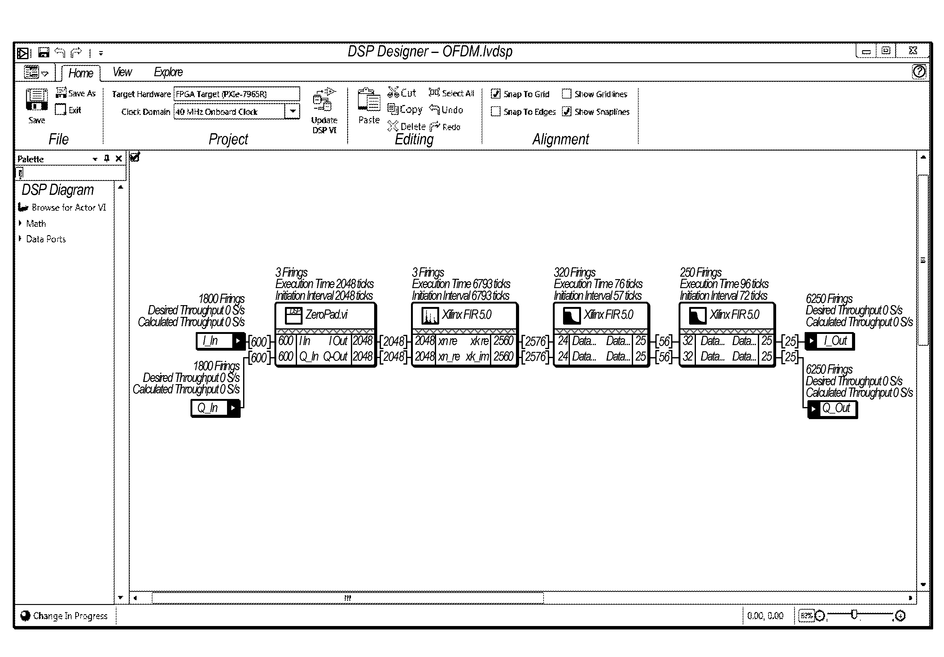
System and method for specifying and implementing programs. A graphical program is created in a graphical specification and constraint language that allows specification of a model of computation and explicit declaration of constraints in response to user input. The graphical program includes a specified model of computation, a plurality of interconnected functional blocks that visually indicate functionality of the graphical program in accordance with the specified model of computation, and specifications or constraints for the graphical program or at least one of the functional blocks in the graphical program. The specified model of computation and specifications or constraints are useable to analyze the graphical program or generate a program or simulation.

Description

PRIORITY DATA[0001]This application claims benefit of priority to U.S. Provisional Application Ser. No. 61 / 369,624, titled “Specifying and Implementing Applications Via a Disciplined Design Methodology”, filed on Jul. 30, 2010, whose inventors are Michael J. Trimborn, Jacob Kornerup, Jeffrey N. Correll, Kaushik Ravindran, Guoqiang Wang, Guang Yang, Sadia B. Malik, Hugo A. Andrade, and Ian C. Wong, and which is hereby incorporated by reference in its entirety as though fully and completely set forth herein.FIELD OF THE INVENTION[0002]The present invention relates to the field of programming, and more particularly to a system and method for specifying and implementing programs.DESCRIPTION OF THE RELATED ART[0003]Many industrial applications require high-performance and / or efficient implementation, such as, for example, digital signal processing (DSP) applications. Moreover, such applications may be subject to various constraints, e.g., with respect to timing, resource usage, throughpu...

Claims


Application Information

Patent Timeline
Patent Type & Authority Patents(United States)
IPC IPC(8): G06F9/44
CPCG06F8/34G06F8/20G06F9/4436G06F2217/74G06F17/30294G06F2217/02G06F17/5045G06F2217/06G06F9/44G06F3/048G06F2217/14G06F2217/16G06F2217/04G06F17/5004G06F2217/12G06F17/30572G06F9/4494G06F16/26G06F16/212G06F30/13G06F30/30G06F30/333G06F2111/02G06F2111/04G06F2111/10G06F2111/12G06F2111/20G06F2119/18
Inventor CORRELL, JEFFREY N.
Owner NATIONAL INSTRUMENTS
Learn More