
Standard graphics specification and data binding

a graphics specification and data binding technology, applied in the field of rendering graphic displays, can solve the problems of application being unable to use graphics files, no name standardization,

Active Publication Date: 2008-10-28
MICROSOFT TECH LICENSING LLC
View PDF20 Cites 4 Cited by
  • Summary
  • Abstract
  • Description
  • Claims
  • Application Information

AI Technical Summary

Problems solved by technology

A problem exists because there may be no standardization for the names of the various sections of data in the graphics file.
An application may not be able to use a graphics file that was not specifically written for the application because the application may not be able to discern which values to set into what named section of the graphics file's data section.

Method used


Image

  • Standard graphics specification and data binding
  • Standard graphics specification and data binding
  • Standard graphics specification and data binding

Examples


example embodiments

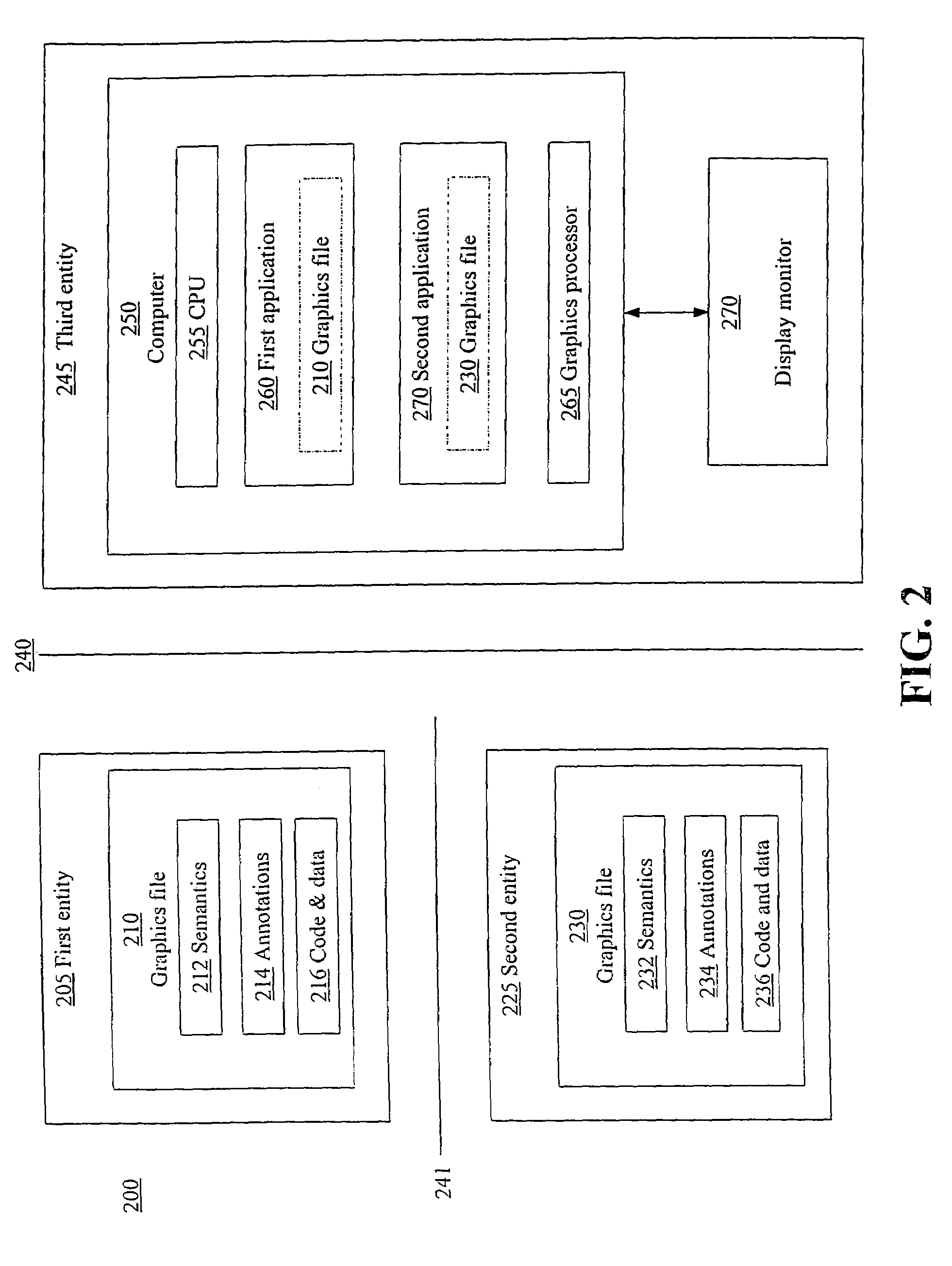
[0027]FIG. 2 is a block diagram of an example system 200 for providing compatibility between independently-developed graphics files and runtime environments. The system 200 may include a first entity 205, a second entity 225, and a third entity 245. Each of the first, second, and third entities 205, 225, 245 may be independent of the other and have no, limited, or full knowledge of the other entities in the system 200. The lines 240, 241 denote that each of the first second, and third entities 205, 225, 245, while included for explanatory purposes in the system 200, may act independently of each other to perform its role in the system 200. Each of the entities 205, 225, 245 does not need to know anything, according to one embodiment of the invention, about the other entities in the system 200.

[0028]The first entity 205 may be, for example, a graphics developer or a game developer that develops a graphics file 210. The graphics file 210 may be any file including information that, whe...


PUM


Abstract

A standard graphics specification for use by both developers of graphics files as well as of applications developed to execute in a runtime environment is disclosed. The graphics files are developed to conform to the graphics specification and therefore will be executable by applications in any runtime environment that likewise conform to the graphics specification. The specification includes program syntax standards and standards for metadata in the form of semantics and annotations that further describe the code. The specification additionally includes standards to which applications may conform to ensure that the applications will be capable of executing any graphics files that conform to the graphics specification.

Description

FIELD OF THE INVENTION[0001]The invention generally relates to rendering graphic displays and specifically to standardizing graphics files and runtime environments to promote compatibility between the two.BACKGROUND OF THE INVENTION[0002]A graphics application may be executed on a computer and may result in rendering a graphic display on a computer monitor or other display. The graphics application may include program code for various aspects related to the rendering. For example, one part of the program code may be related to mesh, another part may be related to lighting, and another part may be related to texture. To render a graphic on a display, the program code may be sent from a graphics file to a video card and may include a pixel, vertex, and other types of shader as well as values for the render state, mesh, lighting, and texture, which are consumed by the shaders. The graphics file thus includes a structure for setting the state of the video card and the code and data used...

Claims


Application Information

Patent Timeline
Patent Type & Authority Patents(United States)
IPC IPC(8): G06F17/00
CPCG06T15/00G06T2210/32
Inventor ARONSON, DAVID FLOYDBLEISCH, PAUL L.HOROWITZ, DANIEL PAULSTEED, JONATHAN THOMAS
Owner MICROSOFT TECH LICENSING LLC
Learn More