
Automatic vascular model generation based on fluid-structure interactions (FSI)

a technology of fluid structure interaction and vascular model, applied in the field of automatic vascular model generation based on fluid structure interaction, can solve the problems of insufficient detection and diagnosis methods, insufficient understanding of plaque rupture responsible for stroke or cardiac arrest, and current technology for diagnosing applicable cardiovascular diseases, etc., to achieve automatic and accurate modeling of mechanical distribution(s)

Active Publication Date: 2013-10-08
WORCESTER POLYTECHNIC INSTITUTE
View PDF8 Cites 91 Cited by
  • Summary
  • Abstract
  • Description
  • Claims
  • Application Information

AI Technical Summary

Benefits of technology

[0013]Advantageously, Applicant's invention employs a 3D model of a blood vessel that includes fluid-structure interactions (e.g., blood-vessel interactions) and the structure of the vessel. The 3D models of the invention further include various components of the vessel, e.g., various plaque components for atherosclerotic plaques. Therefore, the invention can automatically and accurately model mechanical distribution(s), such as stress / strain distribution(s), in the vessel under investigation. Also, Applicant's invention can identify a factor, such as a mechanical biological index, to quantify the degree of the disease status, which can help physicians in decision-making processes.

Problems solved by technology

However, the mechanisms causing plaque rupture responsible for a stroke or cardiac arrest are poorly understood, and available screening and diagnostic methods are insufficient to identify the victims before the event occurs.
For example, current technology for diagnosis of applicable cardiovascular diseases (e.g., carotid plaque rupture, coronary plaque rupture and aneurysm rupture) generally lacks accurate and reliable computational mechanical analysis.
Clinically available magnetic resonance imaging (MRI), computed tomography (CT), and ultrasound medical image equipment do not have computational mechanical analysis and related predictive computational indices for physicians to use in their decision making process.
Even if some of the equipment may have some measurement data derived from some computational models, those models are overly simplified.
However, they are not generally adequate for decision-making purposes.

Method used


Image

  • Automatic vascular model generation based on fluid-structure interactions (FSI)
  • Automatic vascular model generation based on fluid-structure interactions (FSI)
  • Automatic vascular model generation based on fluid-structure interactions (FSI)

Examples


embodiment 100

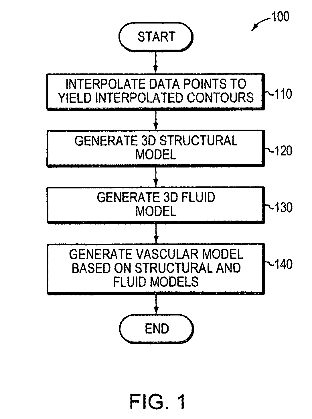
[0040]FIG. 1 is a flow diagram of an embodiment 100 of the invention, which is a process that transforms raw data into a 3D vascular model, i.e., a model representing 3D characteristics of a blood vessel including fluid-structure interactions (FSIs). The raw data may include contour data describing the geometric configuration of plaques within the blood vessel, as well as material properties and other indicators such as blood pressure. Data points corresponding to a contour of a blood vessel are interpolated (110) to yield an interpolated contour. Such interpolation occurs for various contours in a 2D slice of data, which may be obtained via an earlier data collection step. A structural model, representing three-dimensional structural characteristics of the blood vessel, is generated (120) based on multiple interpolated contours corresponding to different 2D slices. A fluid model that represents 3D characteristics of fluid flow within the vessel is also generated (130). Finally, a v...

embodiment 200

[0042]FIG. 2 is a flow diagram showing an end-to-end analytical framework in accordance with an embodiment 200 of the invention. In this framework, M2VPA is one component of the framework, along with input data and a finite element simulation software, such as the commercial finite-element package ADINA® (Adina R&D, Inc., Watertown, Mass., USA). Data corresponding to plaque geometries, i.e., contour data, as well as material properties and blood pressure, are input for processing (210). Known user interface techniques for prompting user entry of these data are utilized. M2VPA performs operator-assisted automatic mesh generation (220) using a technical computing environment, such as MATLAB® (The Mathworks, Inc. Natick, Mass., USA) and exports ready-to-run simulation data, such as ADINA®-readable data, for 2D solid, 3D solid-only, 3D fluid-only, and vascular (FSI) models (230). The finite element simulation software performs computational simulations, e.g., to compute 2D / 3D stress and...

embodiment 400

[0047]FIG. 4 is a block diagram of the main modules of an embodiment 400 of the invention. The four main modules are: (1) a first module 410 for data transformation and processing; (2) a second module 420 for 3D structure reconstruction; (3) a third module 430 for fluid domain reconstruction; and (4) a fourth module 440 for critical mechanical condition analysis.

[0048]The first module 410 performs data input and pre-processing, including interpolation of data points along contours. The second module 420 creates component-fitting lines and surfaces for each 2D slice, connects slices, makes surfaces linking slices, and forms component-fitting volumes; generates a mesh for every volume created; and assigns material properties to each volume. The third module 430 is similar to the second module 420, but applies to the fluid domain. The second module 420 and the third module 430 generate data used to solve a 3D fluid-structure interaction (FSI) model. Typically, modules 420 and 430 gener...


PUM


Abstract

A computer system and method are disclosed for automatically generating a vascular model of a blood vessel to support, for example, identification of mechanical factors corresponding to the blood vessel. The method includes interpolating data points corresponding to a contour of the blood vessel; generating a structural model representing three-dimensional structural characteristics of the blood vessel based on interpolated contours; generating a fluid model representing three-dimensional characteristics of fluid flow within the vessel; and generating a vascular model based on the structural model and the fluid model. The method may also include performing a mechanical analysis of the vascular model to identify a mechanical factor associated with the vessel, for example, a factor associated with a potential plaque rupture within the vessel. Embodiments of the invention are applicable to the diagnosis, assessment, or treatment of cardiovascular diseases.

Description

RELATED APPLICATION(S)[0001]This application is the U.S. National Stage of International Application No. PCT / US2010 / 024527, filed Feb. 18, 2010, which designates the U.S., published in English, and claims the benefit of U.S. Provisional Application No. 61 / 208,501, filed Feb. 25, 2009. The entire teachings of the above applications are incorporated herein by reference.GOVERNMENT SUPPORT[0002]The invention was supported, in whole or in part, by a grant DMS-0540684 from the National Science Foundation and a grant NIH / NIBIB, 1 ROI EB004759 from the National Institutes of Health. The Government has certain rights in the invention.BACKGROUND OF THE INVENTION[0003]Cardiovascular disease (CVD) is the No. 1 killer in the United States. More than 60% of all myocardial infarctions are caused by rupture of a vulnerable plaque. A large number of victims of the disease, who are apparently healthy, die suddenly without prior symptoms. About 95 percent of sudden cardiac arrest victims die before re...

Claims


Application Information

Patent Timeline
Patent Type & Authority Patents(United States)
IPC IPC(8): G06F19/00G06K9/20A61B5/02G06K9/00G06K9/36
CPCA61B6/466A61B8/06A61B8/13A61B8/483G06T17/20G06F19/3437G16H50/50
Inventor TANG, DALINTENG, ZHONGZHAO
Owner WORCESTER POLYTECHNIC INSTITUTE
Learn More