Packaging structure of low-pressure molded fuel cell

a fuel cell and packaging technology, applied in the field of fuel cells, can solve the problems of reduced capacity, electrolyte leakage, electrolyte in the cell diffuse, etc., and achieve the effects of preventing the air cathode from breaking and deforming, good tensile strength and pressure resistance, and good viscosity and elasticity

Inactive Publication Date: 2013-10-08
HIGH TECH BATTERY INC
View PDF8 Cites 5 Cited by
  • Summary
  • Abstract
  • Description
  • Claims
  • Application Information

AI Technical Summary

Benefits of technology

[0011]A primary object of the present invention is to provide a packaging structure of a low-pressure molded fuel cell to effectively remove air bubbles in the sealant used to seal the fuel cell, so that the sealant can perfectly cover the cell components and seal the cell to achieve the purpose of leak prevention with a simplified process.

Problems solved by technology

However, when the zinc contacts with the alkaline electrolyte, there would be a side reaction in which a part of the zinc is corroded so as to cause reduction of the capacity, and hydrogen gas is also produced so as to increase the internal pressure of the cell, further resulting in the electrolyte leakage, that is, the electrolyte in the cell diffuses out to the housing or even to an external circuit interface.
The electrolyte leakage problem will adversely shorten the shelf life of the cell and cause an environmental pollution issue.
It is therefore an important issue among fuel cell manufacturers to effectively prevent electrolyte leakage.
However, none of these cell packages can establish completely sealing for the cell.
In the above-mentioned fuel cell packaging manners, either riveting or compressing the gasket or using more than one sealant to seal the cell, none of them can achieve an exact sealing and leak-proof effect.
(1) In the above riveted structure, an intermediate gasket is compressed using a riveting pressure to seal the cell. While the compressed gasket provides good sealing effect at the beginning, it gradually loses the sealing effect after it has been used over a long time due to aging thereof. While the sealant has been used to reinforce the sealing effect of the compressed gasket, it fails to completely solve the leakage problem of the electrolyte; it is caused by increasing internal pressure of the cell.
(2) The air cathode is a porous structure having a plurality of micropores, and thus there produces a lot of air bubbles to run into the sealant while the air cathode is contacted and covered with the sealant, and particularly is completely covered by the sealant. No matter to use any sealant in the process of molding the cell for the purpose of sealing the cell, the air bubbles in the pores would diffuse into the sealant (i.e. the air bubbles to run into the sealant from the pores) as time goes by. Therefore, it is difficult to effectively remove the air bubbles using a common packaging method. The air bubbles would decrease the packaging strength of the sealant or form leakage channels between the cell and the external environment so as to cause leakage of the electrolyte.
(3) The air cathode is made of carbon, a polytetrafluoroethylene (PTFE) binder and a catalyst, and has relatively low mechanical strength. Therefore, the air cathode is easily deformed when being bent by an external force, and the interface between the air cathode and the sealant is easily deformed due to the thermal expansion and contraction. Moreover, since the material properties of the air cathode and the sealing are different, an interface between the air cathode and the sealant tends to crack, which results in the leakage of the electrolyte from the cell. In fact, the air cathode in contact with the separator consists of a hydrophilic carbon material, which will absorb the electrolyte and form a diffusion channel for the electrolyte. Therefore, the prior art cell packaging manner by compression could not effectively prevent the electrolyte from leakage at all.
(4) The air cathode is a porous structure having the micropores that allow air to freely move in and out to perform the cell reaction. However, during the reaction, zinc oxide products would be gradually deposited on the separator and form a dense structure so as to block the separator. Thus, zinc oxide having the dense structure would become a barrier that blocks the gas, thereby resulting in excessively increasing internal pressure of the cell. The higher the internal pressure of the cell, the larger the deformation of the cell, thereby causing the leakage of the electrolyte.
(5) The existing packaging structure of the zinc-air cell is manufactured by a composite method, such as riveting and adhesive sealing, or adhesive sealing and ultrasonic welding. Such composite packaging structure involves complicated assembly or requires precision equipment so as to increase the structural complexity and cost of the manufacturing device. In addition, the more the types of sealants are used, the easier the electrolyte leakage occurs. Moreover, the sealants are different in their physical and chemical properties, and hence the electrolyte leakage of the zinc-air cell would occur due to the variation of the temperature, vibration, and the other environmental factors.
However, the suggested packaging manner lies in adhering or caulking the cell components with the hot melt adhesive without really achieving the target of effective sealing and electrolyte leakage prevention.

Method used


Image

  • Packaging structure of low-pressure molded fuel cell
  • Packaging structure of low-pressure molded fuel cell
  • Packaging structure of low-pressure molded fuel cell

Examples


Embodiment Construction

[0041]The present invention will now be described with some preferred embodiments thereof. For the purpose of easy to understand, elements that are the same in the preferred embodiments are denoted by the same reference numerals.

[0042]The term “electrolyte leakage” used herein refers to the leakage of the alkali-electrolyte form the cell. The term “C-sectioned” of “C-sectioned annular structure” used herein refers that the cross-section view of the hot melt adhesive layer in the fuel cell shows a C-shaped pattern. The term “C-sectioned flow channel” used herein refers to a flow channel with a C-shaped cross-section formed by assembling the first receiving spaces, air cathode, separator and the second receiving spaces together.

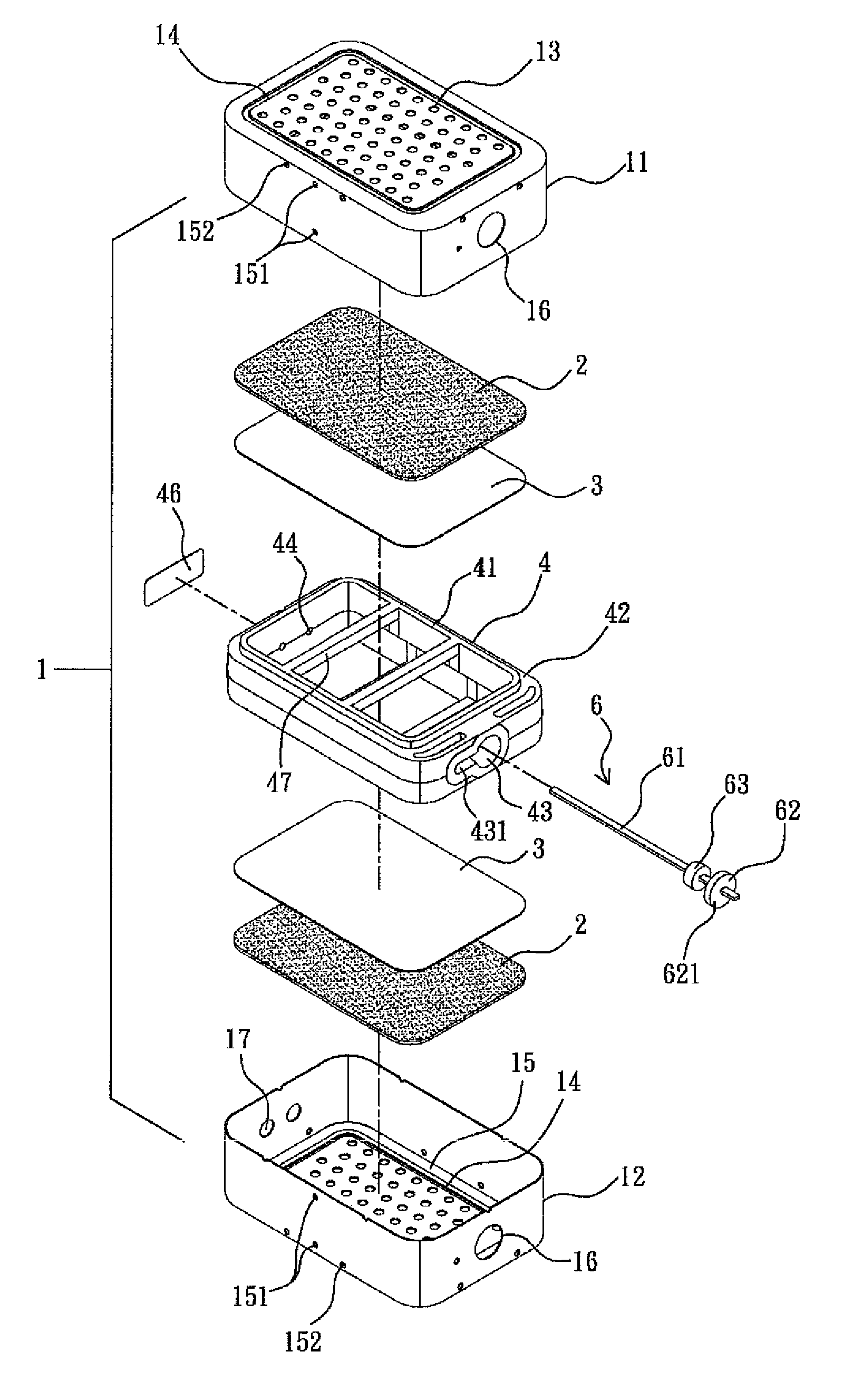
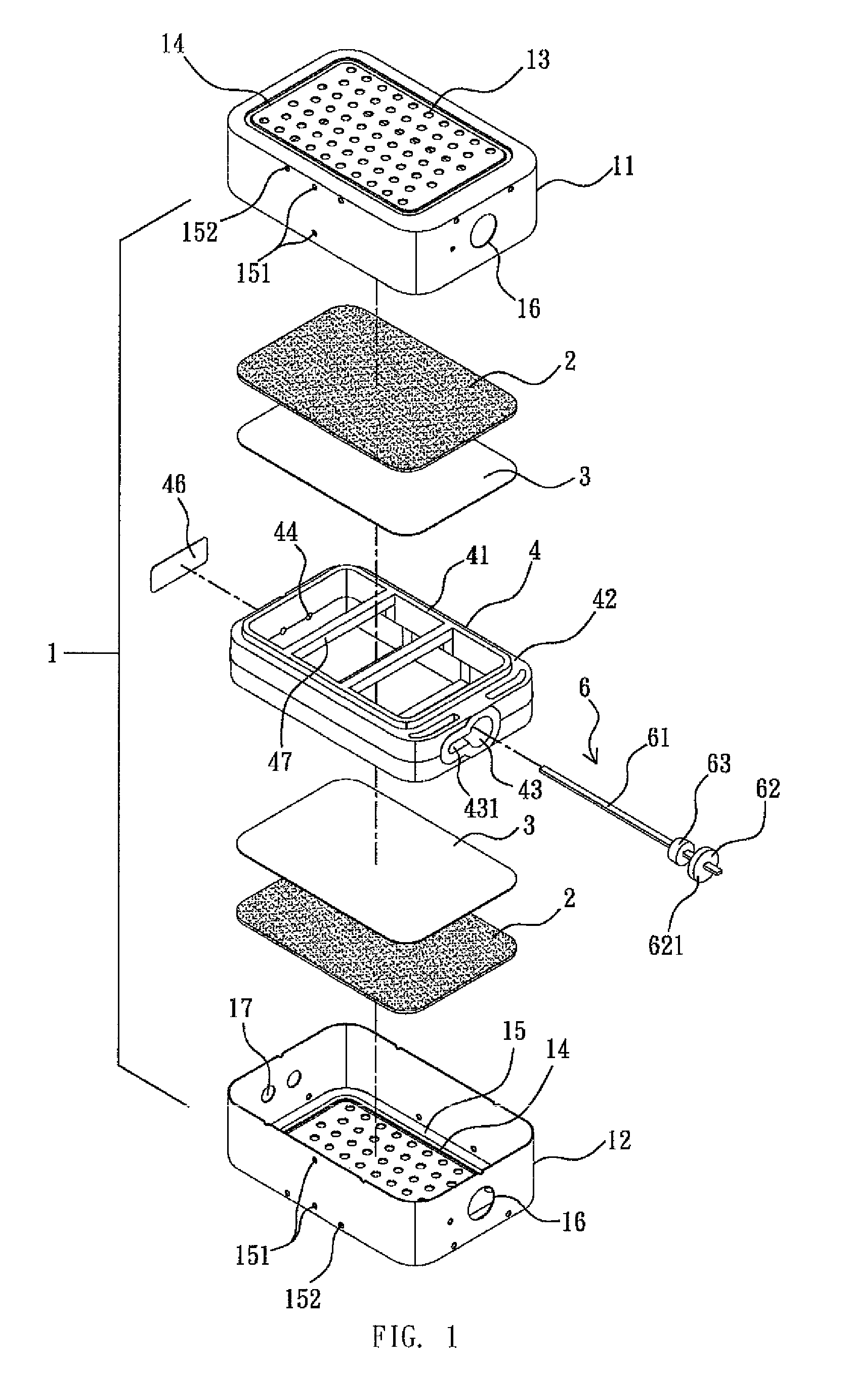
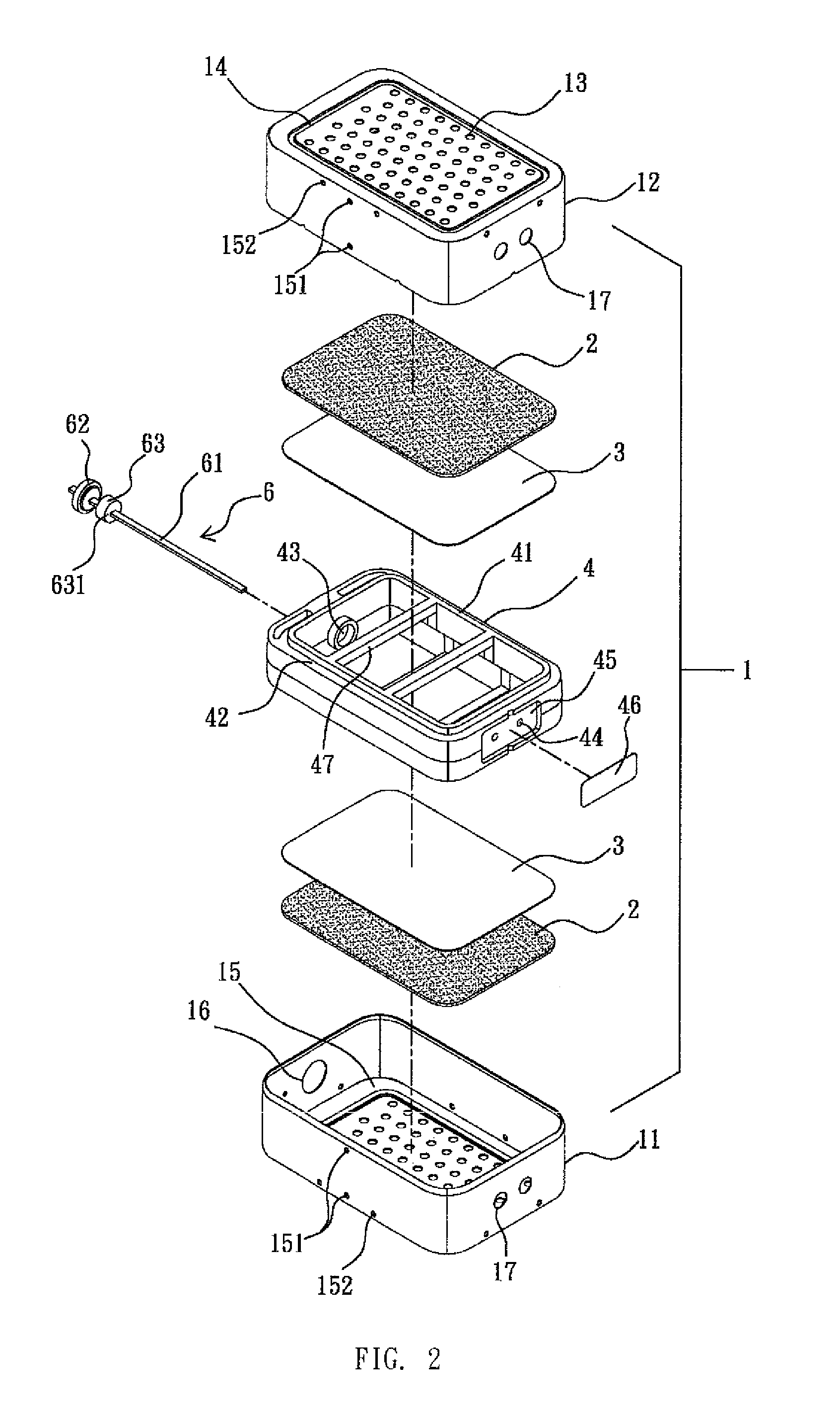
[0043]Please refer to FIGS. 1 to 5. A packaging structure of a low-pressure molded fuel cell according to a first embodiment of the present invention, which can be, for example, a packaging structure of a low-pressure molded zinc-air cell, substantially compris...


PUM

PropertyMeasurementUnit
adhesive viscosityaaaaaaaaaa
elongationaaaaaaaaaa

Abstract

A packaging structure of a low-pressure molded fuel cell comprises a hot melt adhesive layer, which is formed through a low-pressure molding process using a hot melt adhesive that has specific material properties and will become molten when being heated. The molten hot melt adhesive is injected into the cell via injection holes formed on a housing or a mounting element to flow through a C-sectioned flow channel, so as to tightly enclose and bond to edges of the air cathode and separator for the cell. After the hot melt adhesive is solidified, a chemical-resistant hot melt adhesive layer with good sealing and enclosing ability as well as high adhesion strength and elasticity, being bubble removed at controlled pressure and the hot melt adhesive material is formed to firmly bond to the cell components and tightly seal the cell, so as to effectively prevent electrolyte in the cell from leaking.

Description

FIELD OF THE INVENTION[0001]The present invention relates to a fuel cell, and more particularly to a packaging structure of a fuel cell formed by low-pressure molding technique for preventing electrolyte leakage.BACKGROUND OF THE INVENTION[0002]A currently commercially available fuel cell, such as a zinc-air cell, includes a housing, a cathode, a separator and an anode. The zinc-air cell generates electricity through an electrochemical reaction which provides a usable electric current flow through an external circuit connected between the anode and the cathode. In order to perform the overall reaction of the zinc-air cell, the cell also needs the electrolyte solution, such as potassium hydroxide, in which the hydroxide ions (OH−) as the charge carries transfers medium between the anode and the cathode. The zinc-air cell uses zinc as an anode, which can be made from a zinc gel, zinc sheet or zinc plate, and the air cathode made of carbon, a polytetrafluoroethylene (PTFE) binder and a...

Claims


Application Information

Patent Timeline
Patent Type & Authority Patents(United States)
IPC IPC(8): H01M2/08
CPCH01M8/028H01M8/0286H01M12/06Y02E60/50
Inventor WANG CHEN, KUEI YUNG
Owner HIGH TECH BATTERY INC
Why Eureka
Try Eureka