
Apparatus and method for minimally invasive implantation of heart assist device

a biotechnology and assistive technology, applied in the field of assistive biotechnology apparatus implantation, can solve the problems of increasing the number of patients suffering from this disease, pain in the procedure, and patients being rendered helpless and immobile with no options, so as to reduce the likelihood of a favorable outcome and add stress on the patient

Active Publication Date: 2013-10-01
CORINNOVA
View PDF4 Cites 4 Cited by
  • Summary
  • Abstract
  • Description
  • Claims
  • Application Information

AI Technical Summary

Benefits of technology

[0012]The present invention facilitates accelerated implantation versus conventional procedures and devices thus reducing the amount of time a critical patient must spend in surgery. Implantation of an apparatus including a deployable device in accordance with the present invention through a left thoracotomy or subxiphoid incision drastically reduces the recovery time and risk of infection for these patients.

Problems solved by technology

There are 800,000 people with end-stage CHF and only 2,200 hearts available for transplant each year, leaving a large number of people suffering from this disease.
Subsequently these patients are rendered helpless and immobile with no options for treatment other than maintenance therapies—and, if the patient is young enough, placement on a cardiac transplant waiting list.
Conventional direct cardiac compression devices, such as the Anstadt cup, require a sternotomy for implantation, which is a very painful procedure.
Disadvantageously, sternotomies result in long recovery times and a high risk of infection.
Further, there is a high risk of complications due to the lengthy surgery required for these unstable patients.
Current approaches to minimally invasive implantation of heart-assist devices of various types suffer the shortcoming of being relatively slow and difficult procedures, resulting in additional stress on the patient and reducing the likelihood of a favorable outcome.

Method used


Image

  • Apparatus and method for minimally invasive implantation of heart assist device
  • Apparatus and method for minimally invasive implantation of heart assist device
  • Apparatus and method for minimally invasive implantation of heart assist device

Examples


Embodiment Construction

[0024]The present invention will now be described more fully with reference to the accompanying drawings, in which preferred embodiments of the present invention are shown. The present invention may, however, be embodied in many different forms and should not be constructed as limited to the embodiments set forth herein; rather, these embodiments are provided so that this disclosure will be thorough and complete, and will fully convey the scope of the present invention to those skilled in the art.

[0025]The present invention is directed to a minimally invasive implantation apparatus and method and is adapted to save the lives of CHF patients and dramatically shorten their hospital stays. With the present invention, in combination with drug therapy and an exercise program, many of the patients receiving a deployed device, such as a cardiac compression device, in accordance with the present invention, could have restored cardiac function in as little as three weeks, allowing a shorter ...


PUM


Abstract

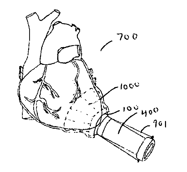
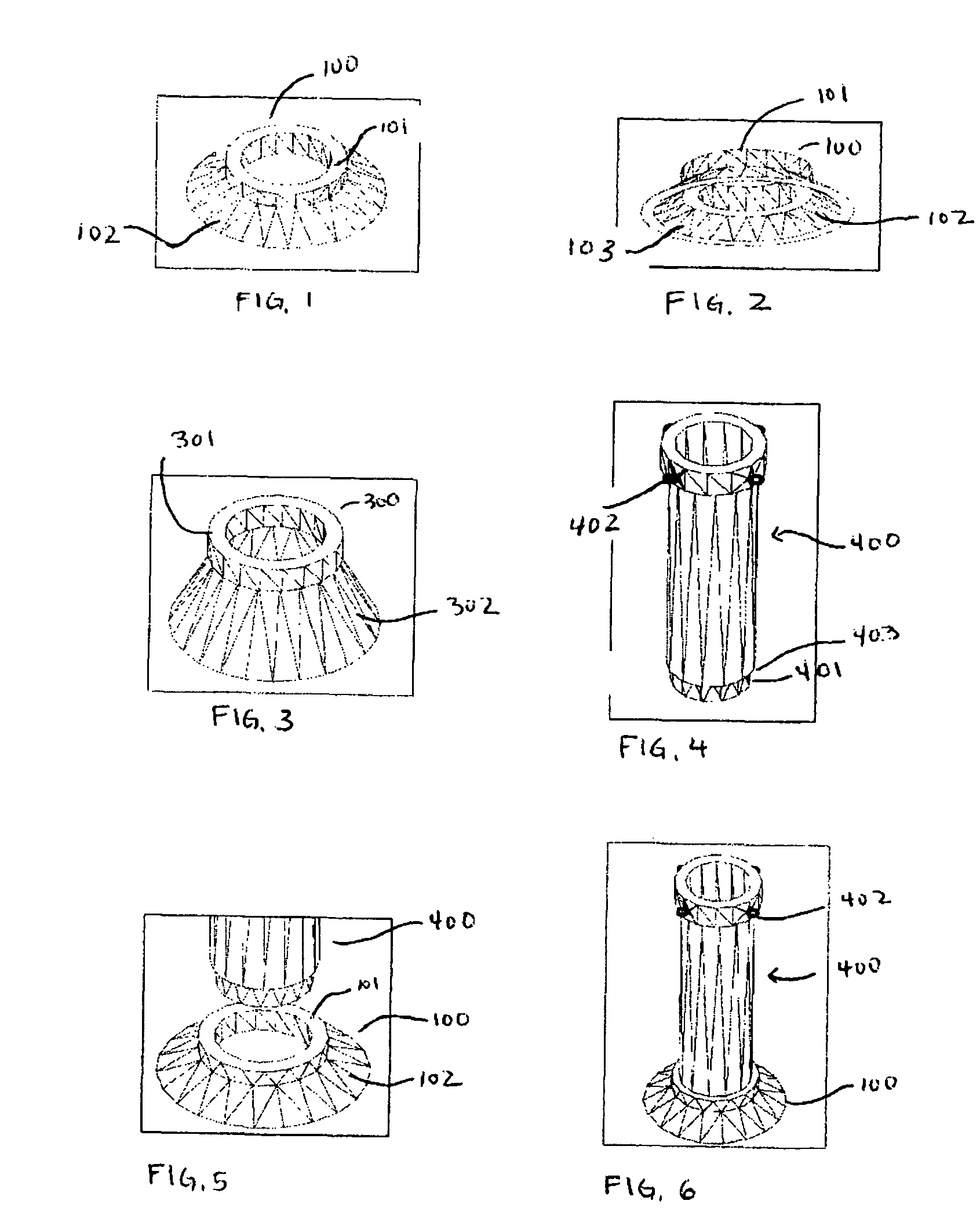
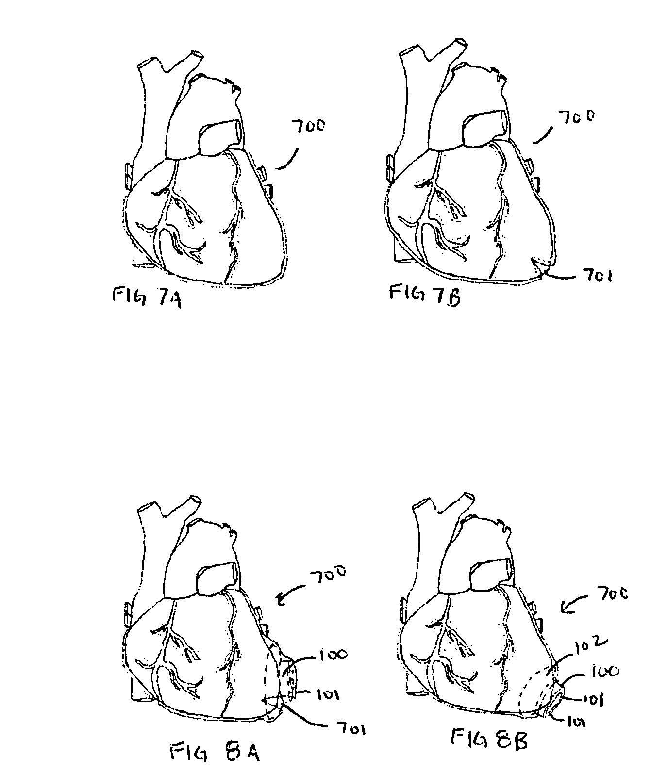
A method and related apparatus for the minimally invasive implantation about a heart of at least a deployable device such as a heart assist device or cardiac compression device. The method comprises the steps of performing a left thoracotomy or subxiphoid incision; obtaining access to the pericardial sac; making a generally linear incision in the pericardial sac; positioning an assembly having an insertion aperture member with an upper ring and a lower ring or flange and insertion tube having therein a deployable device. The apparatus of the present invention includes an insertion aperture member having an upper ring and a lower ring or flange; and an insertion tube having therein a deployable device adapted to be deployed from the insertion tube inside the pericardial sac via a generally linear incision.

Description

CROSS REFERENCE TO RELATED APPLICATION[0001]This application claims the benefit of U.S. Provisional Application No. 61 / 001,733 filed on Nov. 5, 2007, entitled “APPARATUS AND METHOD FOR MINIMALLY INVASIVE IMPLANTATION OF HEART ASSIST DEVICE.”FIELD OF THE INVENTION[0002]The present invention relates to implantation of an assistive biotechnology apparatus, including associated device and method adapted to restore heart function to those who having insufficient cardiac output.BACKGROUND[0003]The left ventricle is the large, muscular chamber of the heart that pumps blood out to the body. Congestive heart failure (CHF) is a condition in which the heart can't pump enough blood to the body's other organs. It is a complex multi-factorial disease which often begins after an index event such as a severe heart attack which produces an initial decline in pumping capacity of the heart. There are 800,000 people with end-stage CHF and only 2,200 hearts available for transplant each year, leaving a ...

Claims


Application Information

Patent Timeline
Patent Type & Authority Patents(United States)
IPC IPC(8): A61B17/00
CPCA61B17/3468A61F2/2481A61F2002/2484
Inventor HARRISON, LEWISHALL, STANLEY DEANROBBINS, DENNIS
Owner CORINNOVA
Learn More