
Device and method for performing end-to-side anastomosis

a technology of end-to-side anastomosis and suture, which is applied in the field of end-to-side anastomosis devices and methods, can solve the problems of high risk of distal thrombosis, various blood damage, and critical patient mortality and morbidity, and achieve the effect of reducing the amount of time required and simplifying the suture delivery

Inactive Publication Date: 2006-07-27
ARCIA ROVIL P +2
View PDF2 Cites 128 Cited by
  • Summary
  • Abstract
  • Description
  • Claims
  • Application Information

AI Technical Summary

Benefits of technology

[0007] The present invention comprises systems, methods, and kits for facilitating the suturing of one body duct to another body duct or tissue surface. The present invention simplifies suture delivery, reducing the amount of time required for performing an anastomosis and facilitating the delivery of suture needles through blood vessels. The present invention may be used in a variety of environments and is applicable to both stopped heart and beating heart procedures. The prevent invention may be used in a minimally invasively environment using percutaneous ports such those developed by Heartport, Inc. of Redwood City, Calif. or retractor systems developed by Cardio Thoracic Systems of Cupertino, Calif. Of course, the present invention may also be used in an open surgery environment.
[0008] The present invention preferably allows thee delivery of a plurality of needles through both body ducts in a single continuous motion by the user. Advantageously, this simplified needle / suture delivery reduces the amount of time spent on performing body duct connections such as an anastomosis. In situations where the invention is used with a beating heart, the invention allows for rapid actuation once the device is properly positioned, reducing the likelihood that movement of the beating heart may misposition the device during actuation. The present invention further allows for the simultaneous delivery of a plurality of needles through the body ducts in an evenly-spaced manner which thus improves the quality of the anastomosis by having a consistent suture pattern and a calculated tissue capture. The present invention is also particularly useful when targeting a pressurized blood vessel when it is desirable to maintain hemostasis at the targeted suture site.

Problems solved by technology

The amount of time spent performing these anastomosis procedures to connect blood vessel grafts between blocked arteries and pressurized blood supplies is critical to patient mortality and morbidity.
Continual circulation of blood through the mechanical apparatus of the bypass machine can cause various degradations to the blood.
Perhaps the most prevalent complication arising from prolonged cardiac bypass is the high risk of distal thrombosis, which can embolize into the neurovasculature and potentially cause a stroke.
In “off pump” procedures where patients are not placed on cardiopulmonary bypass and the heart remains beating, the difficulty of suturing an anastomosis graft on a moving surface of the heart may degrade the quality of such grafts completed on patients.
It can be appreciated that some of the sutures are easily made from on top of the conduit or blood vessel graft, while others are more difficult to complete as they are beneath the conduit.
It can be further appreciated that performing such complex suturing procedures on a moving platform, such as the beating heart, further increases the difficulty associated with such suturing procedures.
Improperly connecting blood vessel grafts to the patient may present substantial post-operative complications and / or increase operating room time spent correcting the improperly connected graft.

Method used


Image

  • Device and method for performing end-to-side anastomosis
  • Device and method for performing end-to-side anastomosis
  • Device and method for performing end-to-side anastomosis

Examples


Embodiment Construction

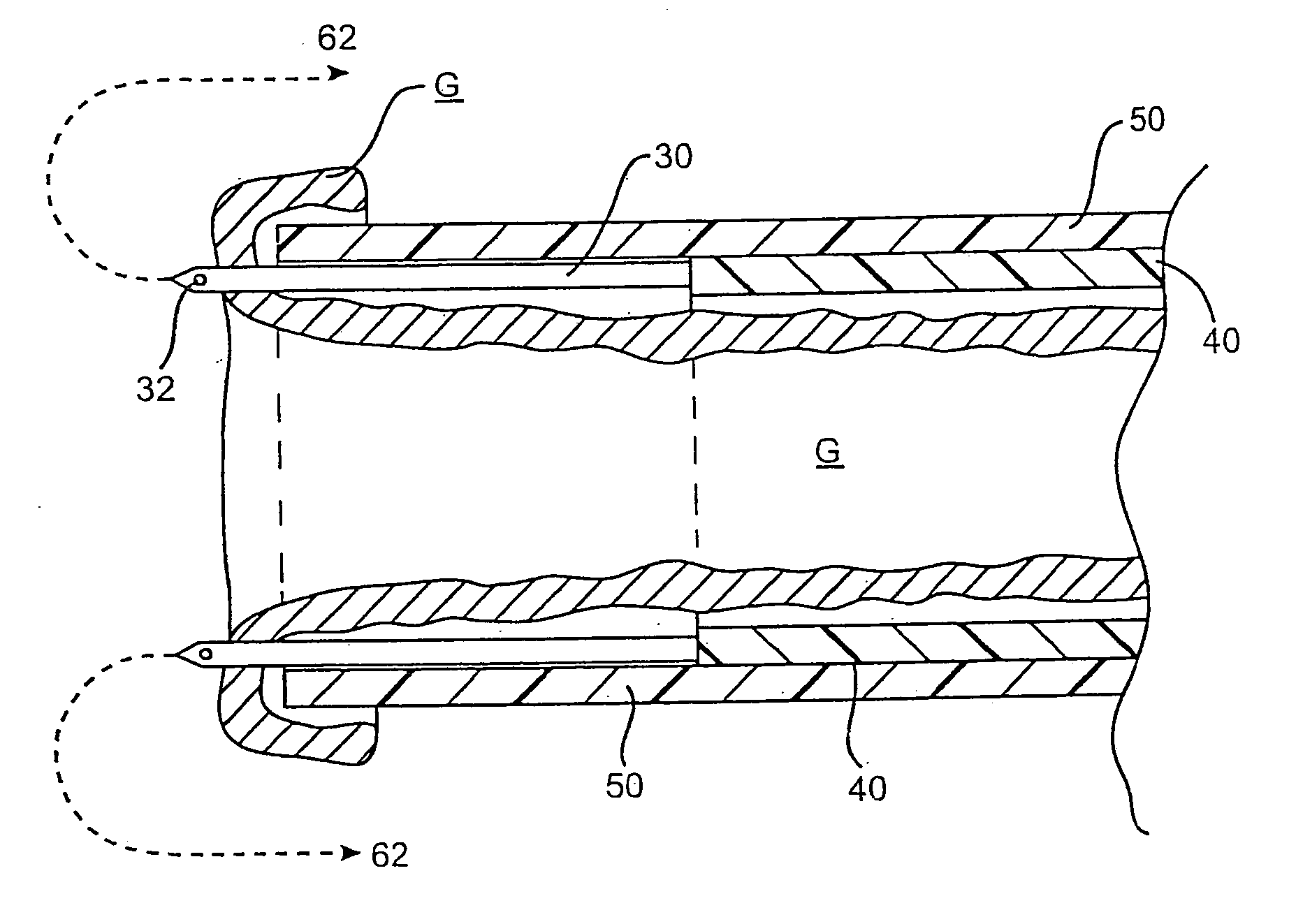
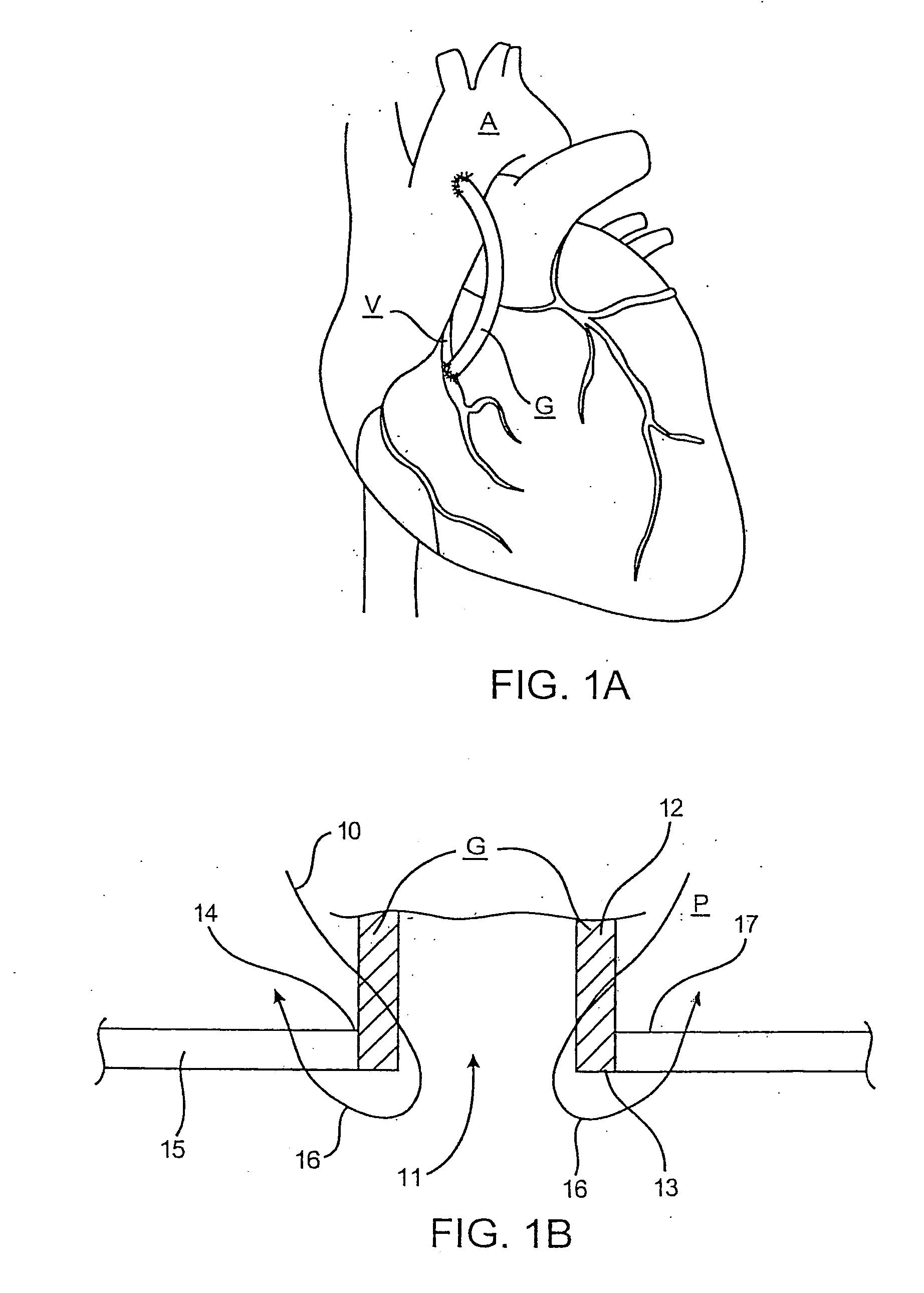
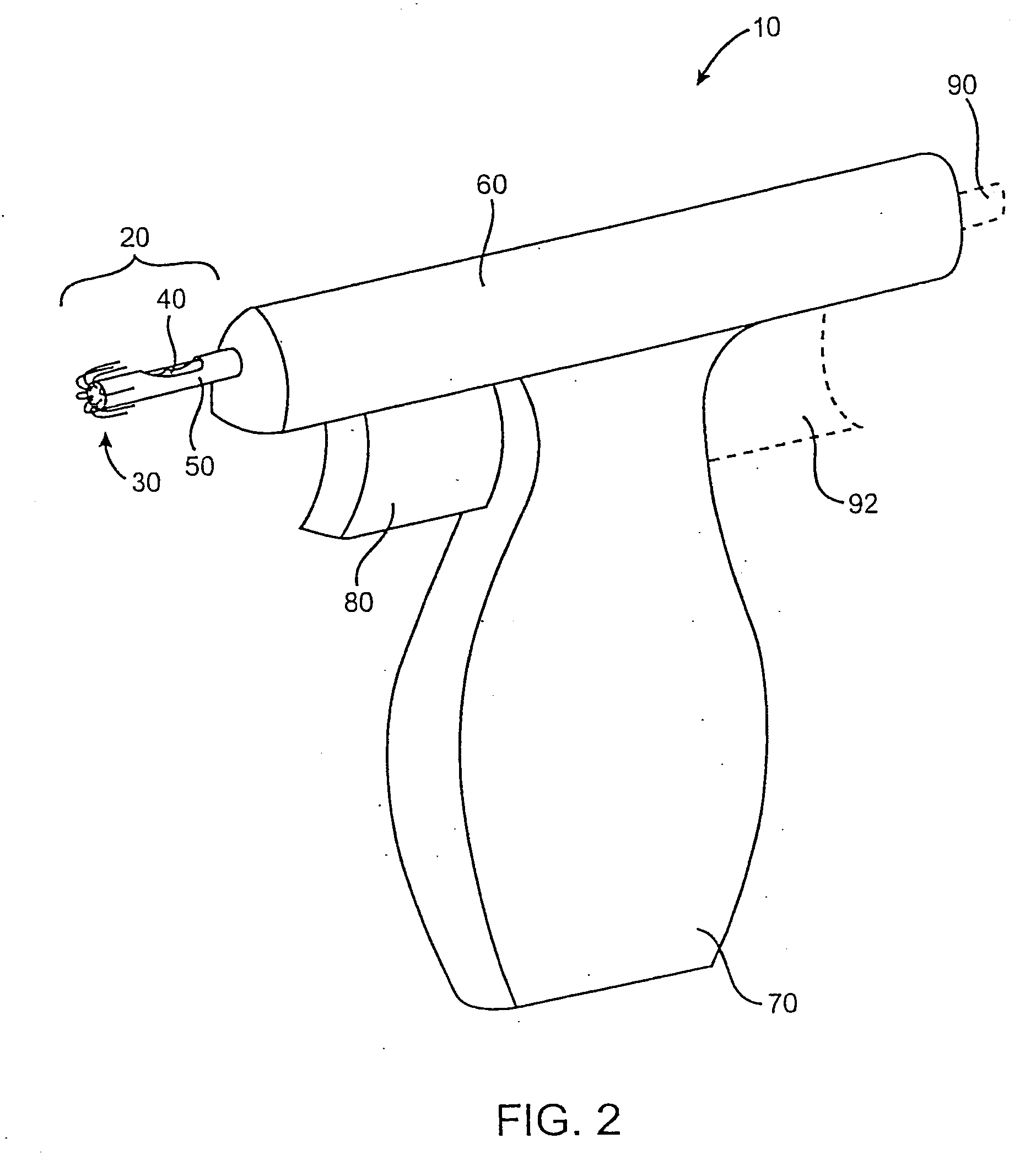
[0029] The present invention is directed towards devices and methods for facilitating the suturing of one body duct to another body duct. In particular, the present invention will facilitate the end-to-side or end-to-end anastomosis of a vascular graft such as a saphenous vein to a target artery such as the aorta or similar blood vessel. Usually, a vascular graft will have a width in the range from 2 mm to 8 mm, while the target will have a width from 2 mm to 5 mm. The aorta will have a width from 20 mm to 40 mm. As described below, devices of the present invention can preferably deploy a plurality of needles in an evenly spaced or otherwise predetermined configuration to perform the anastomosis. In exemplary embodiments, a device of the present invention can position the suture for performing the end-to-side anastomosis through one hand stroke or step by the user. Deployment of a plurality of needles in a predetermined pattern increases the likelihood that that the anastomosis will...


PUM


Abstract

Devices, methods, and kits are provided for suturing an end of a first body duct to a hole in the side of a second body duct. The present devices and methods are used to simplify the suturing procedure and thus reduce operating time. In one embodiment, the present device includes a structure for holding the end of the first body duct and positioning the end adjacent to the hole in the side of the second body duct. The structure of the device is typically a shaft having a surface adapted to receive the first body duct. A plurality of needles are arranged on the structure to be advanced along a plurality of paths. Each needle path first passes radially into and forwardly out of the end of the first body duct and into the hole of the second body duct. The path then everts so that the needles and associated sutures will pass outwardly through tissue peripheral to the hole when the end of the first body duct is on the structure adjacent to the hole in the second body duct. The needles preferably travel along such paths when they are advanced forward. In one embodiment, the device uses a J-shaped tube for guiding one of the needles along the desired path. In another embodiment, shape-memory needles having an arcuate profile are used to create the desired path.

Description

CROSS-REFERENCES TO RELATED APPLICATIONS [0001] The present application is related to commonly assigned, copending U.S. patent applications Ser. No. 08 / 824,031 (Attorney Docket No.15508-000140US) filed on Mar. 26, 1997, Ser. No. 08 / 883,246 (Attorney Docket No. 15508-000150US) filed on Jun. 26, 1997, and Ser. No. ______ (Attorney Docket No. 15508-003100) filed on the same day as the present application. The full disclosures of each of these application are incorporated herein by reference.BACKGROUND OF THE INVENTION [0002] The present invention relates generally to devices and methods for suturing body tissue. More particularly, the present invention is useful for performing end-to-side attachments of body ducts, such as in suturing coronary blood vessel grafts. [0003] In many medical procedures today, it is desirable to connect a body duct, such as a hollow organ or blood vessel, to a targeted piece of tissue. In coronary surgery, this type of attachment is commonly referred to as a...

Claims


Application Information

Patent Timeline
Patent Type & Authority Applications(United States)
IPC IPC(8): A61B17/04
CPCA61B17/0469A61B17/0482A61B17/11A61B2017/00867A61B2017/047A61B2017/0472A61B2017/06028A61B2017/1107A61B2017/1135A61B2017/1139
Inventor ARCIA, ROVIL P.LICHTENSTEIN, SAMMEHL, DOUGLAS
Owner ARCIA ROVIL P
Learn More