
Biodegradable structures for suspending anchor bolts

a technology of anchor bolts and biodegradable materials, applied in the field of concrete form framing and positioning structures, can solve the problems of increasing labor costs, affecting the use of foregoing coordinated combinations, and affecting the environment, so as to achieve the effect of improving the use of the foregoing coordinated combinations

Inactive Publication Date: 2013-10-01
DIAZ MELISSA P MRS
View PDF26 Cites 9 Cited by
  • Summary
  • Abstract
  • Description
  • Claims
  • Application Information

AI Technical Summary

Benefits of technology

The present invention provides an anchor bolt suspending structure made of biodegradable materials that can be easily affixed and removed from both the concrete form and the monolithic pour containment perimeter. This structure protects the exposed threads of the anchor bolts from inadvertent coating by wet cement, and allows for the discarding of the biodegradable parts directly into the form voids. The use of segmented drilling and retainers ensures that the bolt shanks are securely positioned and suspended without interfering with the operation of the form. The coordinated color coding makes it easy for workers to safely affix the suspending structure to the form. The invention is cost-effective and environmentally friendly, with minimal waste and biodegradable materials.

Problems solved by technology

In each instance, form integrity against distortion by the weight of the wet concrete and the correct placement retention of various anchors that are to be captured in the hardened concrete are matters of constant concern as cured concrete is wholly unforgiving.
In large building projects this inattention to inspection convenience tends to raise labor costs as employees and equipment stand by to allow the inspectors to finish their job.
When implemented as permanent tooling these devices often incur the cost and burden associated with inventory maintenance and also its storage and if not properly collected a potential burden on the environment may result.

Method used


Image

  • Biodegradable structures for suspending anchor bolts
  • Biodegradable structures for suspending anchor bolts
  • Biodegradable structures for suspending anchor bolts

Examples


Embodiment Construction

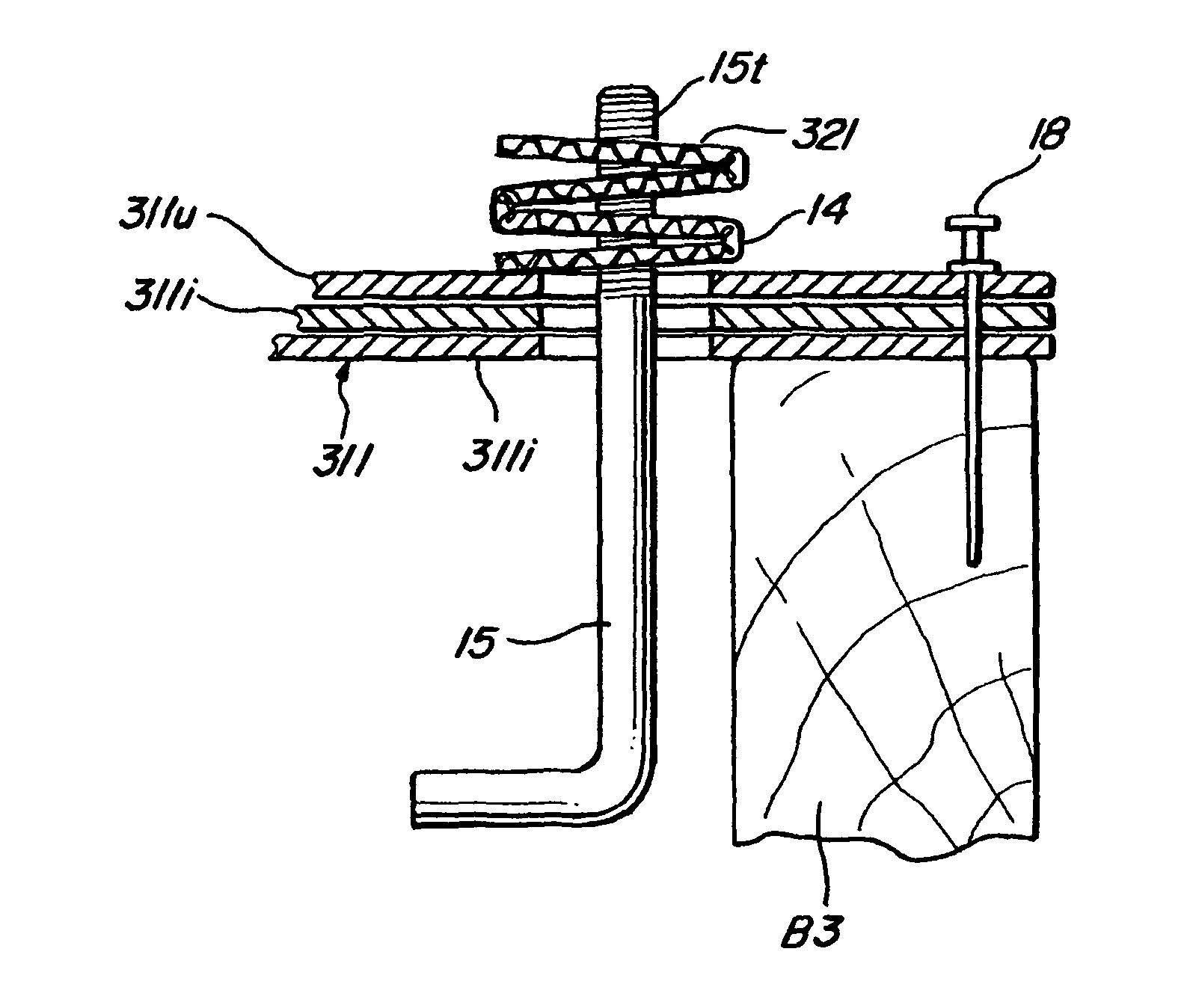
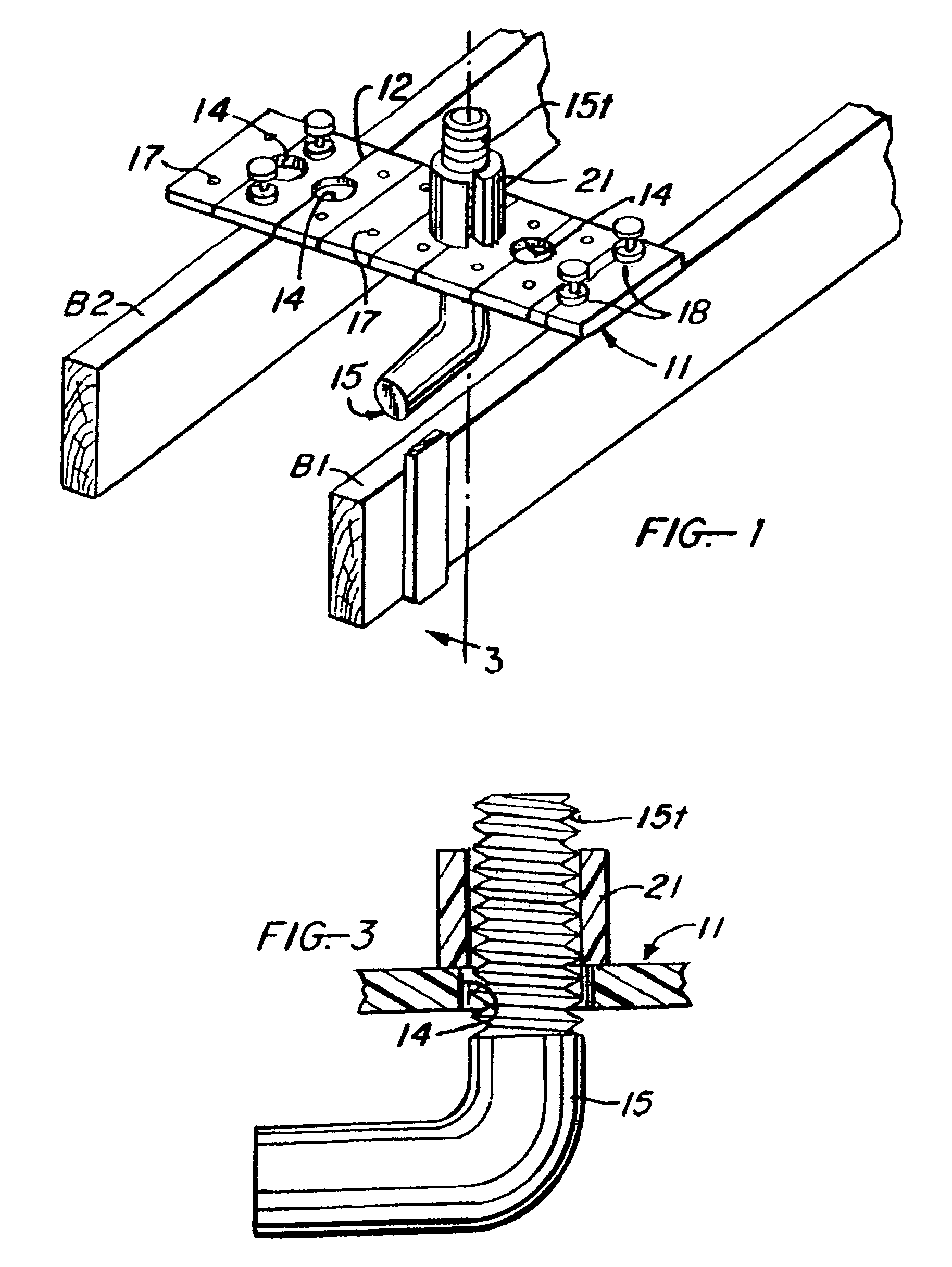
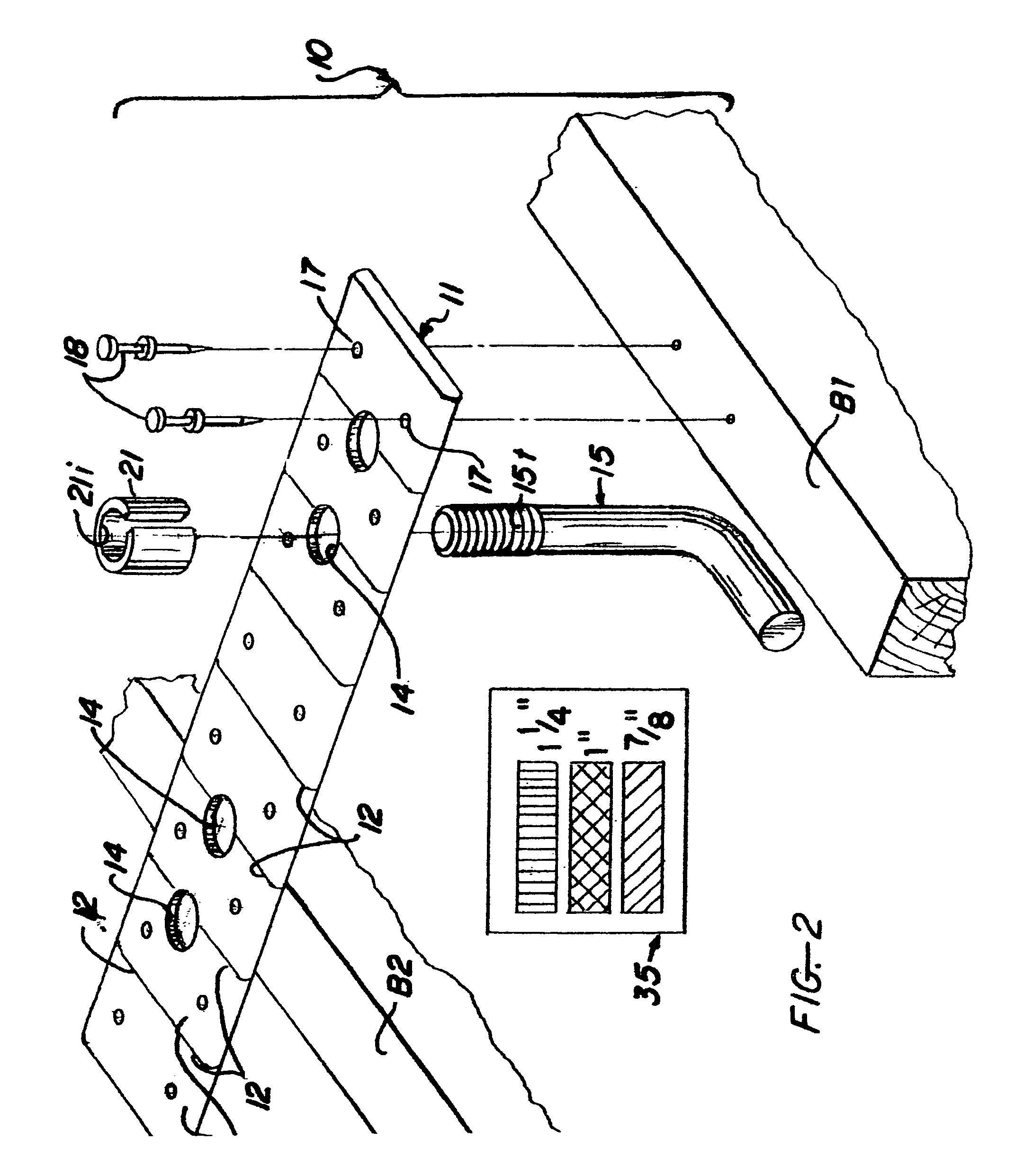
[0039]As shown in FIGS. 1-3, the inventive anchor bolt positioning assembly, in accordance with its first embodiment generally designated by the numeral 10, comprises a substantially rectangular, elongate segment 11 marked on both sides with transversely aligned grooves or guide marks 12 and including spaced along the length thereof a set of equally sized circular openings 14. The threaded portion 15t of the shank or shaft of an appropriately sized anchor bolt 15, sometimes referred to as a J-bolt, is then inserted from below into a selected one of the openings 14 to extend through the plate or segment 11a projecting portion of the shaft for capture in the interior 21i of a resilient, longitudinally split tube section or retainer 21.

[0040]Preferably, the clearance between the opening 14 and the threaded portion 15t of the bolt shaft is less than the wall thickness of retainer 21 and once the threaded shaft portion is resiliently captured therein a retaining engagement of the bolt in...


PUM

PropertyMeasurementUnit
thicknessaaaaaaaaaa
thicknessaaaaaaaaaa
thicknessaaaaaaaaaa

Abstract

An anchor bolt suspending array comprises a biodegradable bridging structure attachable across a concrete form or in cantilever from one side thereof conformed by folding longitudinally a corrugated cardboard panel into overlying segments each provided with a set of spaced openings that are aligned upon folding to receive the shank of an anchor bolt therein. A retainer either formed as a frustoconical cardboard pulp structure dimensioned to capture the anchor bolt shank end, or as an accordion folded corrugated cardboard strip perforated by spaced holes conformed to grasp the shank, is then useful to suspend the bolt from the bridging structure into the poured concrete. Both the retainers and the bridging structures can be color coded by a biodegradable coating in accordance with the size of the anchor bolt that is receivable therein.

Description

REFERENCE TO RELATED APPLICATIONS[0001]This application is a continuation-in-part of my prior U.S. patent application Ser. No. 12 / 322,203, filed Jan. 30, 2009, and now issued as U.S. Pat. No. 7,891,110, which in turn is a continuation-in-part of my earlier U.S. patent application Ser. No. 11 / 823,324 filed Jun. 27, 2007, and now issued as U.S. Pat. No. 7,487,597. The benefit of these earlier filing dates is claimed for all matter common therewith.BACKGROUND OF THE INVENTION[0002]1. Field of the Invention[0003]The present invention relates to concrete form framing and positioning structures, and more particularly to biodegradable structures for bridging concrete forms while securing in such alignment suspended anchor bolts for partial immersion into the poured concrete.[0004]2. Description of the Prior Art[0005]Pouring wet concrete into temporary forms that determine its eventual shape is a process that occurs with substantial frequency in virtually all construction. In each instance,...

Claims


Application Information

Patent Timeline
Patent Type & Authority Patents(United States)
IPC IPC(8): B22D5/00
CPCE04B1/4157E04G21/185Y10T29/49716
Inventor DIAZ, RUDY A.
Owner DIAZ MELISSA P MRS
Learn More