
Heating and cooling control methods and systems

a control method and technology of heat and cooling, applied in the field of heat, ventilation and air conditioning (hvac), can solve the problems of system sampling outside air, non-compliance, and inability to meet, and achieve the effect of improving energy efficiency

Inactive Publication Date: 2013-09-24
KEELING OLIVER JOE +1
View PDF42 Cites 87 Cited by
  • Summary
  • Abstract
  • Description
  • Claims
  • Application Information

AI Technical Summary

Benefits of technology

The present invention provides a user-programmable controller that uses mathematical algorithms to monitor and react to local current ambient air conditions in order to control the use of whole house ventilation as an alternative to HVAC in a whole-building heating and cooling system for improved energy efficiency. The controller can also react to local weather forecasts, current ambient air conditions, and models of building heat retention and loss to optimize the use of fresh air ventilation in combination with heating and cooling cycles. Additionally, the controller can compute building heat-loss models and modify algorithms for an improved overall energy efficiency of the programmable HVAC system.

Problems solved by technology

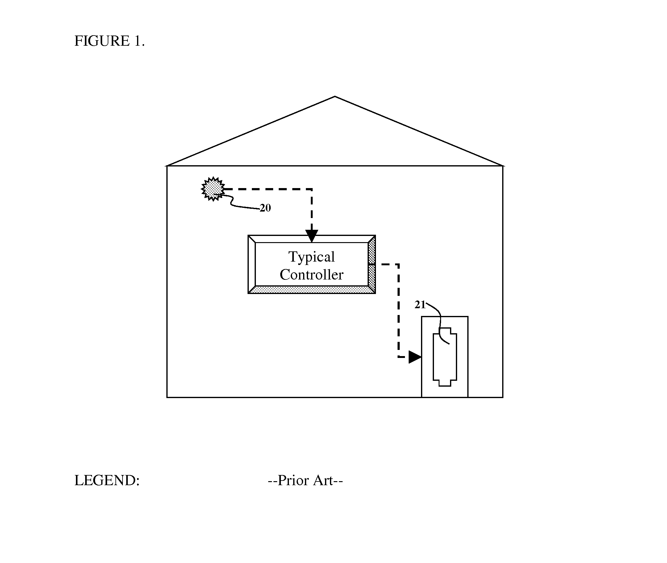
One significant drawback with such HVAC systems is that they do not comply with ASHRAE Standard 62.2 because they typically do not provide any outside ventilation capability.
Importantly it has also meant that indoor air can be stale and some would argue not so healthful.
Such controllers typically prevent the system from sampling outside air when temperatures are below or above a certain limit.
One significant drawback with currently available ventilation with HVAC is too little fresh air ventilation or random timing of control of fresh-air sampling that causes poor energy efficiency in the HVAC system.
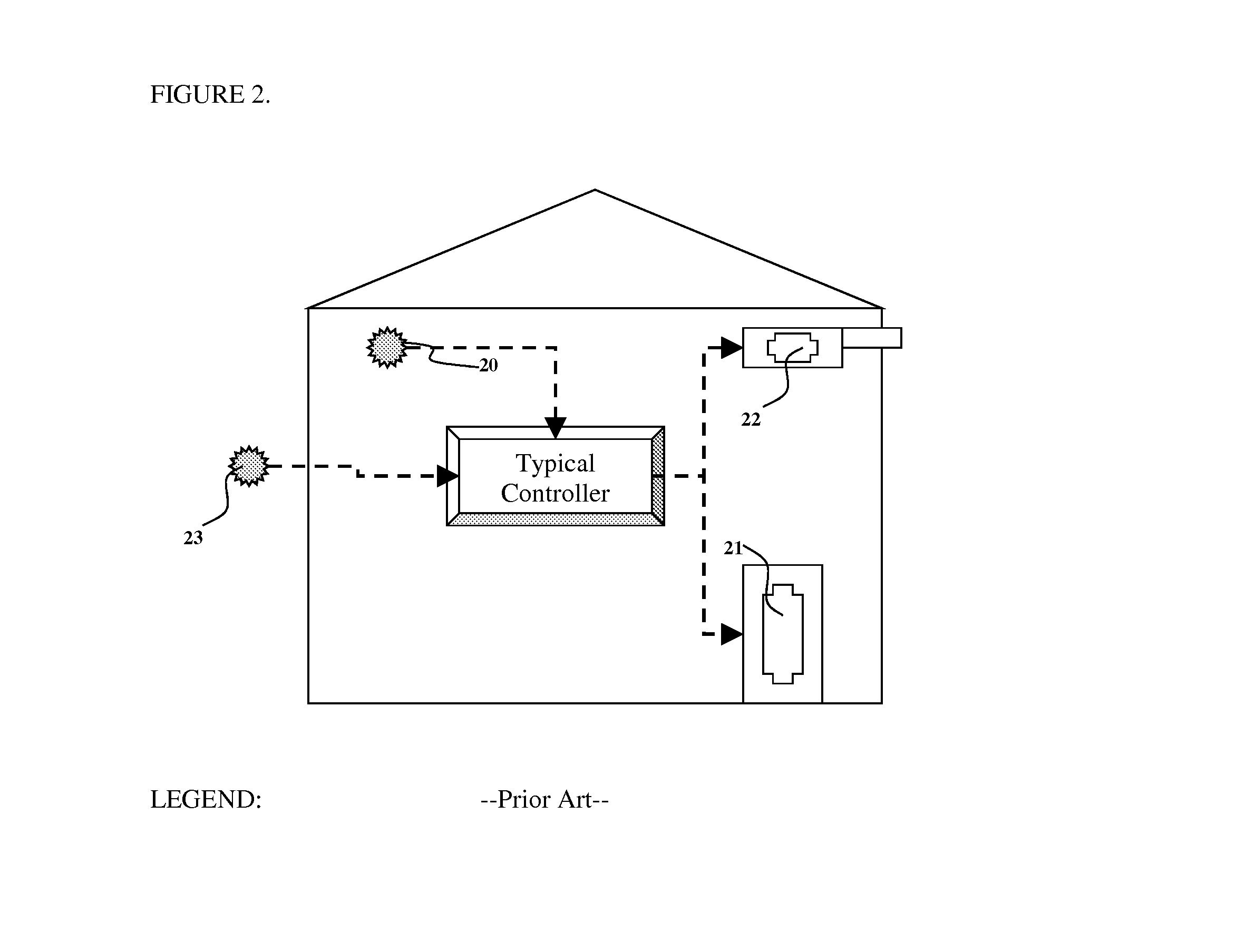
Whilst these improvements in ventilation capability are built into the HVAC system their control is notably not integrated with the HVAC controller.
Whilst this approach is very effective it does not adapt quickly to outside conditions and does not function without active occupant participation and is not inherently optimized to minimize costs.
What is apparent from the literature as well as in fact from a review of existing HVAC control equipment, is the surprising lack of automated integration of mixed-mode heating and cooling using a combination of ventilation and HVAC.
Importantly, in none of these examples is there an attempt to integrate or automate the Whole House Ventilation with an existing HVAC nor is there any integration with the buildings HVAC Control system or control software.
More importantly the Whole House System does not bring together a monitoring system for inside and outside conditions with time and additionally does not integrate this with weather data monitoring to predict an optimal use of outside air.
HVAC engineers continue to research ways to optimize the operation of heating and cooling systems, however despite various publications, practical applications are not apparent.
There exist problems in various aspects of the known technologies, from using more efficient heat exchangers to improved monitoring and the like.

Method used


Image

  • Heating and cooling control methods and systems
  • Heating and cooling control methods and systems
  • Heating and cooling control methods and systems

Examples


example 1

[0051]A whole-house fan (e.g., a typical direct-drive or belt-drive and thermally-protected fan is obtained DIY suppliers) was modified to fit an insulated opening in the ceiling of a conventional insulated two-story timber-framed house. The fan is controlled manually by a hand-held switch and used in conjunction with open or closed windows. The fan is conventional, multi-speed, 3-bladed and capable of blowing air at more than 1,000 cubic feet per minute. By controlling the fan in different environmental conditions throughout the year, we determined that outside air is an effective way of cooling a house when outside temperature and humidity is suitable. The system was not very effective when windows were partially closed and almost completely ineffective when windows were completely closed.

example 2

[0052]Daily maximum and minimum temperature data as well as hourly temperature data for different cities and states were downloaded from publicly available databases (e.g., Iowa Environmental Mesonet). These data were from different years such as 2000, 2001, 2002, 2003, 2004, 2005, 2006, 2007. A computer modeling spreadsheet was devised to evaluate and compare the costs of using a conventional thermostat controller compared with the present invention. The modeling system was also evaluative, allowing different methods of control and different set-points to be evaluated. Using this system we found that energy savings of up to 25% were possible on certain times of day and on different days energy savings of an extra 15% were possible. Savings were not possible on all days of the year but in no case was the present invention less efficient when compared with our model of a conventional thermostatic controller.

[0053]We concluded that the present invention has the potential to decrease e...

example 3

[0054]Thermal heat loss equations (see table below) can be calculated based on Heat Loss equations (Simplified design of HVAC systems. William Bobenhausen, 1994, Technology & Engineering) or U-factors (quantified as BTU / ft2° F.hr). Using information provided in chapter 5 we computed the U-factor for different rooms by using the published BTU / ° F.hr. There was considerable variation between rooms even in the same house (ranging from 0.1 to 0.3 BTU / sq.ft.° F.hr). It is obvious that the range of variation in thermal loss values will be even greater between different houses.

[0055]

Heat Loss(BTU / Surface AreaThermal Loss (UA)° F. hr)(sq. ft)(BTU / sq. ft. ° F. hr)Room A (15 × 10 × 10)46.31500.309Room B (15 × 20 × 10)553000.183Room C (10 × 10 × 10)9.71000.097Room D (15 × 15 × 10)63.32250.281Room E (10 × 15 × 10)401500.267Room F (6 × 15 × 10)14900.156Room G (12 × 15 × 10)23.41800.130Room H (9 × 15 × 10)26.61350.197Total / Average34.913300.203Building Thermal heat loss equation: (QA = U · A · (Ti...


PUM


Abstract

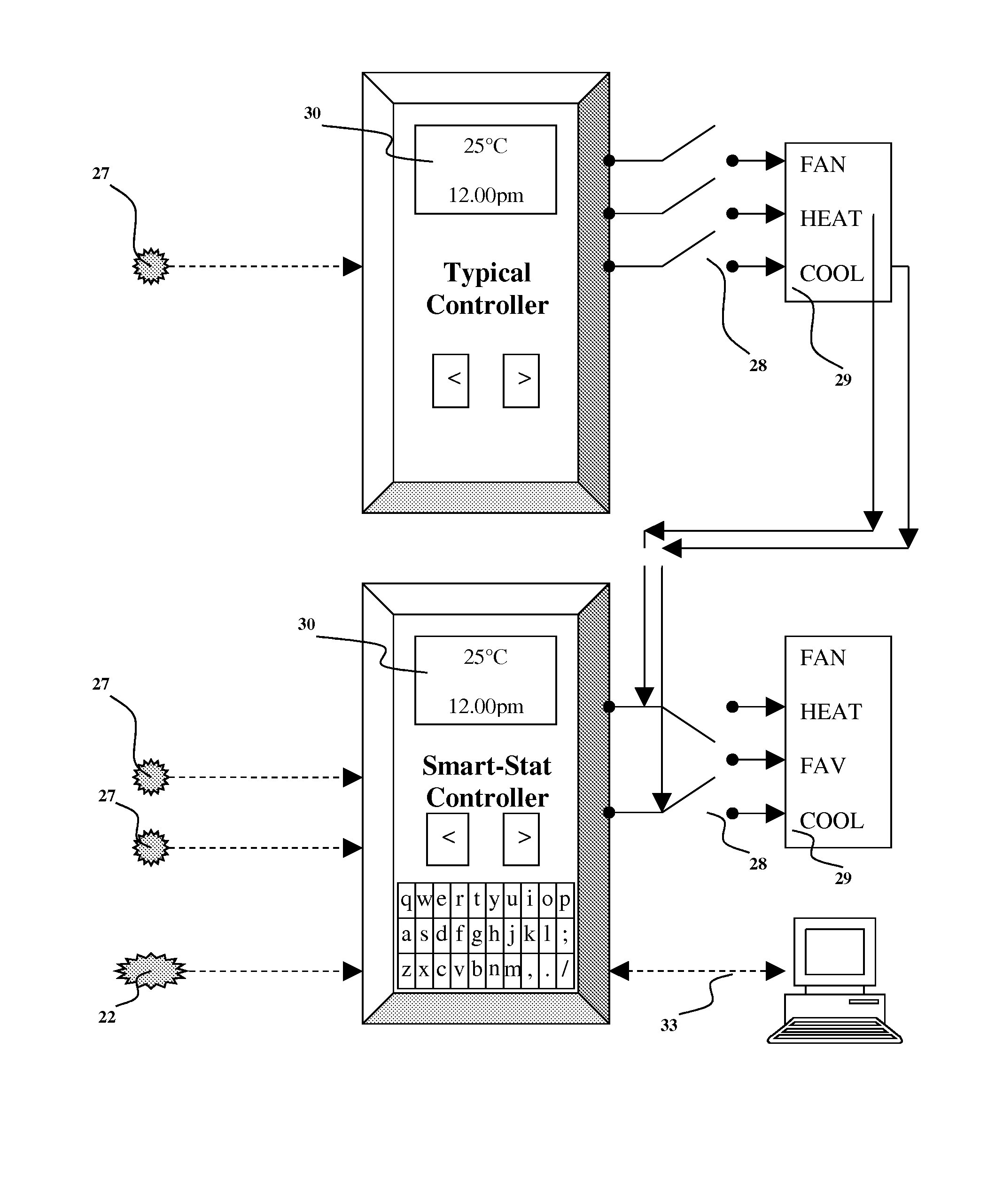
A single controller interface (Smart-Stat) integrates the control of heating or cooling in buildings by simultaneously controlling Heating, Ventilation and Air Conditioning (HVAC) systems in concert with separate fresh air ventilation (FAV) systems. The Smart-Stat reduces costs and the carbon footprint of typical HVAC systems by optimizing the use of FAV. User-programmable set-points are incorporated with time-of-day and day-of-week as well as data from multiple sensors, thermostats and weather information. Mathematical algorithms are used to determine control signals to the HVAC or FAV systems. The Smart-Stat integrates the two separate systems into a single system that is able to direct the call for cooling or heating to the HVAC or FAV systems, depending on appropriate outside weather conditions. Any building can replace its existing HVAC system controller with the Smart-Stat controller and incorporate a FAV system to create a single integrated HVAC and FAV system.

Description

[0001]This is a continuation of Provisional Patent Application U.S. 61 / 139,327 filed Dec 19, 2008.FIELD OF THE INVENTION[0002]The presently claimed invention is related to the field of heating, ventilation and air conditioning (HVAC). More particularly, the presently claimed invention is related to methods and systems for controlled heating and cooling in order to reduce costs and the carbon footprint of said heating and cooling by optimizing the use of fresh air ventilation (FAV).BACKGROUND OF THE INVENTION[0003]Heating, ventilating, and air conditioning (HVAC), sometimes referred to as climate control, involves closely regulating humidity and temperature in order to maintain a comfortable, safe and healthy environment inside a building. HVAC has been described in detail in “Simplified design of HVAC systems” (William Bobenhausen—1994—Technology & Engineering). HVAC system settings are controlled by a thermostat inside a building and typically include a controller device that adjus...

Claims


Application Information

Patent Timeline
Patent Type & Authority Patents(United States)
IPC IPC(8): G05D23/19
CPCF24D19/1066F24F13/0209F24F2011/0058F24F2130/00F24F2130/10F24F11/63
Inventor KEELING, OLIVER JOEKEELING, PETER LEWIS
Owner KEELING OLIVER JOE
Learn More