Modular air inlet lip with electric defrosting for a turbojet pod

a turbojet pod and air inlet technology, which is applied in the direction of jet propulsion plants, power plant arrangements/mountings, air transportation, etc., can solve the problems of affecting the air inlet affecting the aerodynamic properties of the air inlet, and affecting the direction of the fan, so as to improve the ease of replacement of such an air inlet lip

Inactive Publication Date: 2013-09-24
AIRCELLE
View PDF12 Cites 8 Cited by
  • Summary
  • Abstract
  • Description
  • Claims
  • Application Information

AI Technical Summary

Benefits of technology

The present invention proposes an improved design for an air inlet lip of a turbojet pod that can be easily replaced. The lip has at least one electric heating element for de-icing, which can be connected to a power supply connector of the downstream structure. The lip is made up of identical modules that can be easily replaced without changing the undamaged structures. This design reduces the need for spare parts and facilitates the replacement of a damaged part of the lip.

Problems solved by technology

The presence of ice or frost modifies the aerodynamic properties of the air inlet and perturbs the guidance of air towards the fan.
Furthermore, fragments of ice may possibly break away from the air inlet lip and collide with components of the turbojet such as the fan blades.
Moreover, the air inlet lip is a component which is subject to numerous impacts with external elements such as grit, birds, hail, etc., which can damage the aerodynamic integrity of the outer surface and lead to premature wear.
Since the performance of the turbojet is dependent on the quantity and quality of the air capture provided by the air inlet, a defective lip must be replaced as rapidly as possible.
Such a replacement is a time-consuming and expensive maintenance operation, since it is possible for only one part of the lip to be damaged.
This increases the weight of the propulsion unit, which is undesirable.
Although less complicated, the changing of one or more structures is still time-consuming because of the need to reconnect the power supply means of the structure.

Method used


Image

  • Modular air inlet lip with electric defrosting for a turbojet pod
  • Modular air inlet lip with electric defrosting for a turbojet pod
  • Modular air inlet lip with electric defrosting for a turbojet pod

Examples


Embodiment Construction

[0034]Reference will now be made in greater detail to a preferred embodiment of the invention, an example of which is illustrated in the accompanying drawings. Wherever possible, the same reference numerals will be used throughout the drawings and the description to refer to the same or like parts.

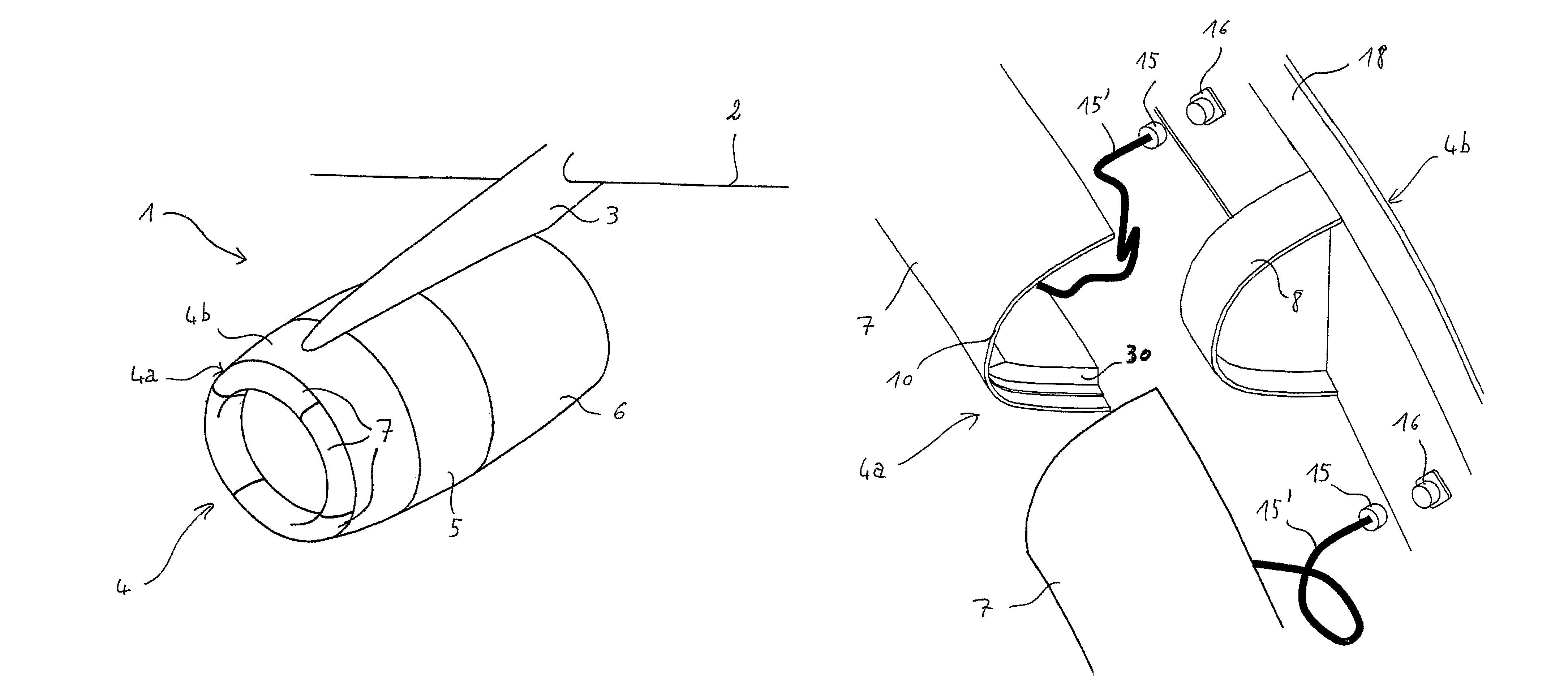
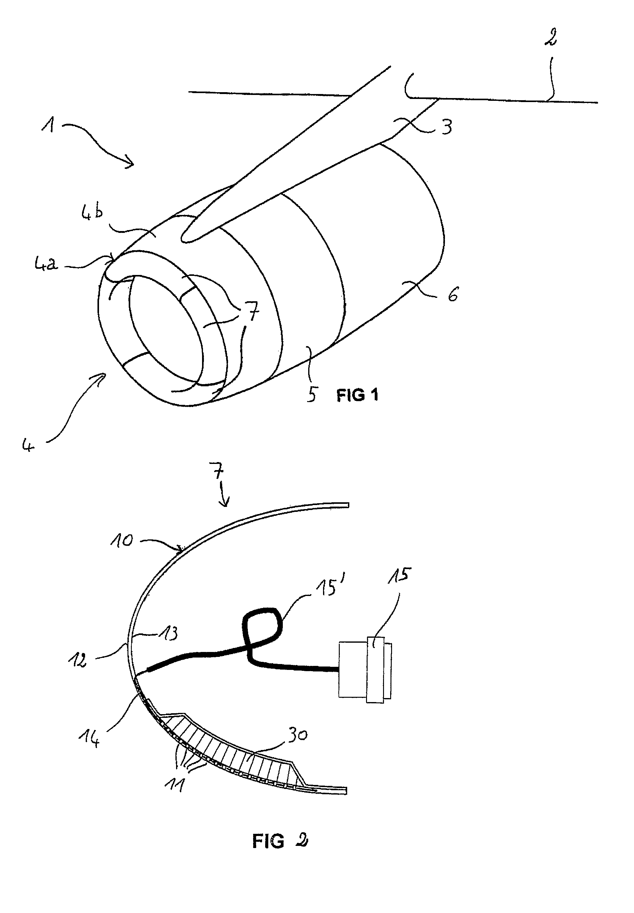
[0035]A pod 1 according to the invention, as shown in FIG. 1, forms a tubular housing for a turbojet (not shown) and serves to channel the air flows generated by the latter. The pod 1 is located under a wing 2 to which it is attached by a pylon 3. It also houses various components required for the operation of the turbojet.

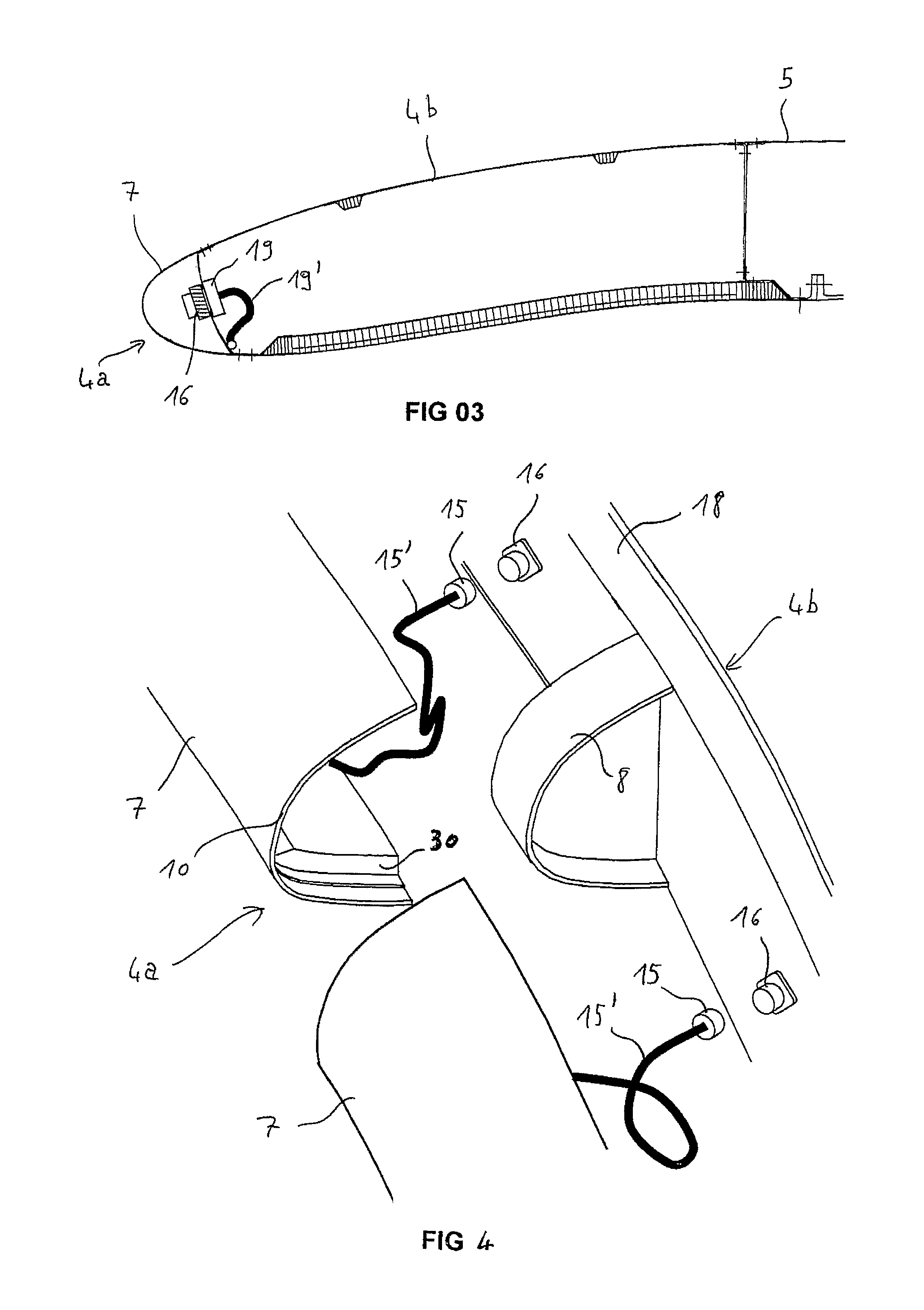
[0036]More precisely, the pod 1 has a structure comprising a forward section forming an air inlet 4, a mid-section 5 enclosing a turbojet fan (not shown), and a rear section 6 enclosing the turbojet and housing a thrust reversal system (not shown).

[0037]The air inlet 4 is divided into two parts, namely, on the one hand, an inlet lip 4a adapted in such a way that the air ...


PUM


Abstract

A lip of an air inlet of a turbojet pod intended to be fastened to an air inlet downstream structure includes at least one electric heating element for defrosting. The electric heating element being fitted with at least one electrical connector able to be connected to at least one corresponding electricity supply connector of the downstream structure. The lip breaks down into at least two identical structures set end-to-end on a periphery of the air inlet.

Description

CROSS REFERENCE TO RELATED APPLICATION[0001]This is a National Stage of International Application No. PCT / FR2007 / 000463, filed 19 Mar. 2007, which claims the benefit of Application No. 06.02548, filed in France on 24 Mar. 2006, the disclosures of these Applications are incorporated by reference herein.BACKGROUND OF THE INVENTION[0002]1. Field of the Invention[0003]The present invention relates to an air inlet lip for a turbojet pod, which is to be attached to a downstream air inlet structure and which comprises at least one electric heating element for de-icing, together with a corresponding downstream structure; the invention also relates to a turbojet pod comprising an air inlet according to the invention.[0004]2. Description of Related Art[0005]An aircraft is propelled by one or more propulsion units, each comprising a turbojet housed in a tubular pod. Each propulsion unit is attached to the aircraft by a pylon which is generally located under a wing or on the fuselage.[0006]The ...

Claims


Application Information

Patent Timeline
IPC IPC(8): B64D33/02
CPCB64D15/12B64D33/02F02C7/047Y02T50/672B64D2033/0233Y02T50/60
Inventor VAUCHEL, GUY BERNARDPORTAL, JEAN-FABRICE MARCELBLIN, LAURENT ALBERTTHOREL, CHRISTOPHE
Owner AIRCELLE
Why Eureka
Try Eureka