
Hydraulic directional valve

a technology of directional valves and valve bodies, applied in the field of valves, can solve problems such as faulty orientation, and achieve the effect of suppressing the relative movement between the filter element and the bulge, and preventing the bottom of the groov

Active Publication Date: 2013-09-17
SCHAEFFLER TECH AG & CO KG
View PDF14 Cites 1 Cited by
  • Summary
  • Abstract
  • Description
  • Claims
  • Application Information

AI Technical Summary

Benefits of technology

The solution effectively maintains stable valve characteristics over the engine's service life by preventing filter displacement and ensuring contaminants are filtered out, thus avoiding throttling and ensuring reliable hydraulic control.

Problems solved by technology

It is disadvantage of this embodiment that in the case of a slight faulty orientation of the annular filter with respect to the valve housing, the transverse struts of the frame element can be arranged radially with respect to the openings of the connections or directly adjacently to the opening of the pressure medium channel which is formed in the cylinder head and with which the annular groove communicates.
The faulty orientation can be caused during operation, for example, by the flow forces of the pressure medium and the play between the annular groove and the frame element.
This results in considerable throttling of the pressure medium flow through the directional valve, which leads to an undesired, temporally variable change in the directional valve characteristics, and therefore in the worst case to the failure of the controller of the connected hydraulic consumer.

Method used


Image

  • Hydraulic directional valve
  • Hydraulic directional valve
  • Hydraulic directional valve

Examples


Embodiment Construction

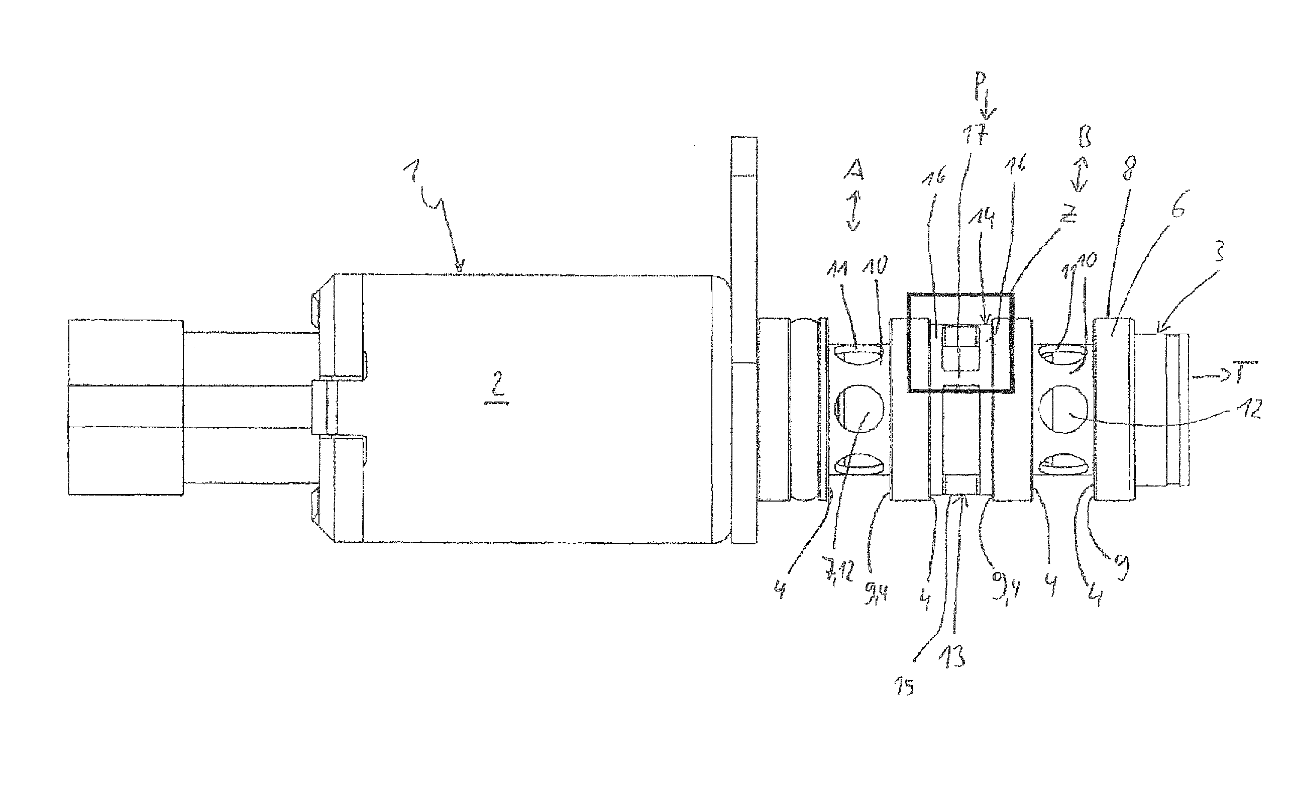
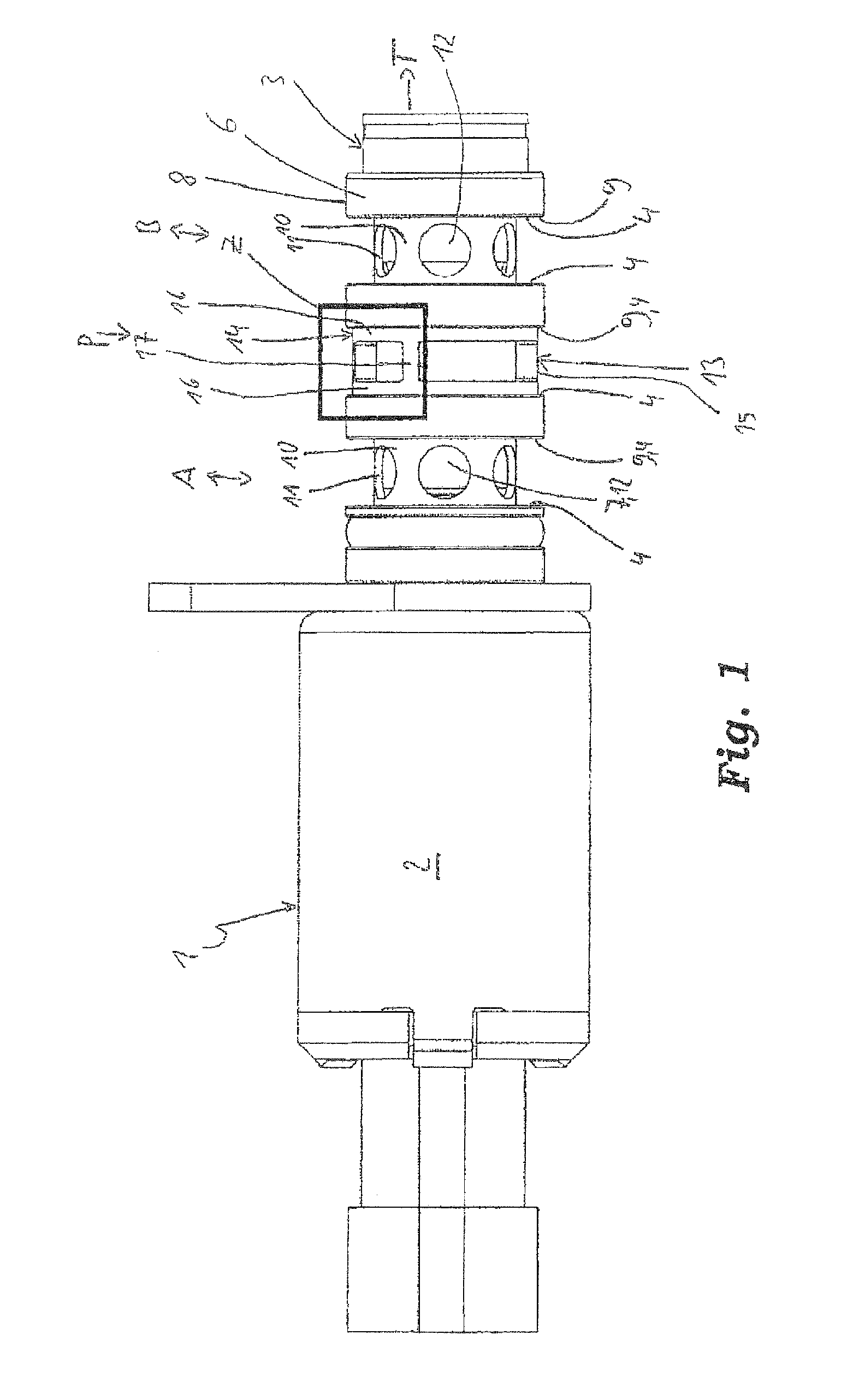
[0028]FIG. 1 shows a hydraulic directional valve 1 according to the invention in a plan view, using the example of a directional valve 1 which is configured as a 4 / 3-way proportional valve. The directional valve 1 comprises an actuating unit 2 and a valve section 3. Directional valves 1 of this type are used, for example, for controlling hydraulic camshaft adjusters.

[0029]The valve section 3 of the directional valve 1 is usually received in a receptacle of a surrounding construction, for example a cylinder head or a cylinder head cover. The valve section 3 has a valve housing 6 of substantially cylindrical configuration and a control piston 7. The valve housing 6 is configured as a separate component and is connected fixedly to the actuating unit 2.

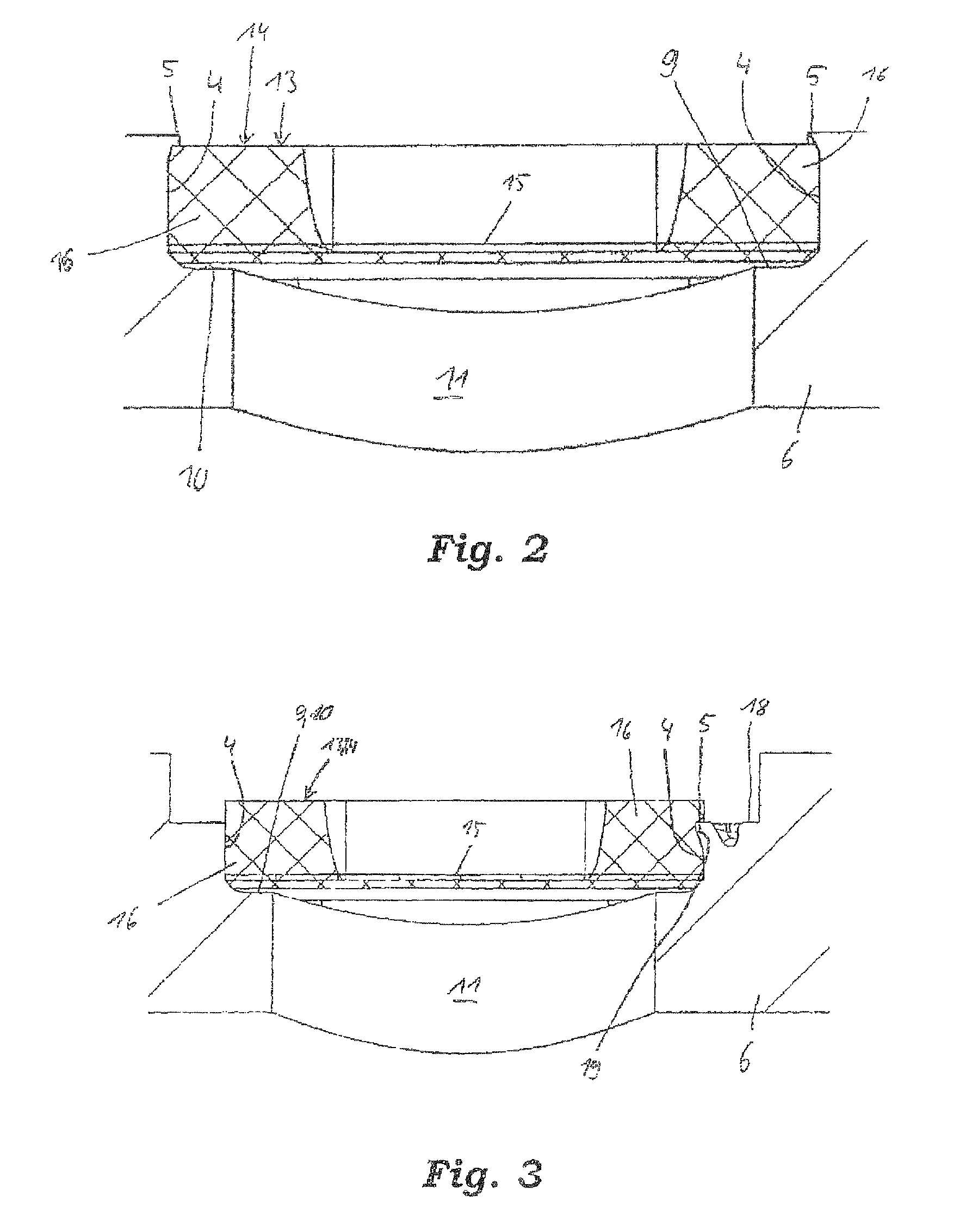
[0030]A plurality of grooves 9, annular grooves in the embodiment shown, are formed on the outer circumferential face 8 of the valve housing 6, which grooves 9 are configured to be open radially to the outside. The grooves 9 are delimited...


PUM

PropertyMeasurementUnit
pressureaaaaaaaaaa
diameteraaaaaaaaaa
internal diameteraaaaaaaaaa

Abstract

A hydraulic directional valve which has a valve housing and a filter element. At least one groove encircles the valve housing and the filter element is arranged in the groove and has at least one frame element and a filter fabric which is firmly connected to the frame element. The groove has a groove base and two side walls which extend substantially in the radial direction and circumferential direction.

Description

[0001]This application is a 371 of PCT / EP2009065156 filed Nov. 13, 2009, which in turn claims the priority of DE 10 2008 060 069.5 filed Dec. 2, 2008, the priority of both applications is hereby claimed and both applications are incorporated by reference herein.FIELD OF THE INVENTION[0002]The invention relates to valves and more particularly to a hydraulic directional valve.BACKGROUND OF THE INVENTION[0003]Directional valves of this type are used in internal combustion engines, for example for actuating hydraulic camshaft adjusters or switchable cam followers, for example switchable drag levers, bucket tappets or roller tappets. The directional valves comprise an actuating unit and a valve section. The actuating unit can be, for example, an electromagnetic or hydraulic actuating unit. The valve section represents the hydraulic section of the directional valve, a feed connection, at least one working connection and a tank connection usually being configured on said section. Defined c...

Claims


Application Information

Patent Timeline
Patent Type & Authority Patents(United States)
IPC IPC(8): F16K11/07
CPCF01L1/34Y10T29/49412Y10T137/794Y10T137/7976Y10T137/86622
Inventor HOPPE, JENSKONIAS, STEFAN
Owner SCHAEFFLER TECH AG & CO KG
Learn More