
Multi-mode interference splitter/combiner with adjustable splitting ratio

a technology of multi-mode interference and splitter, which is applied in the field of optical devices, can solve the problems of difficult tuning of the splitting ratio of mmi devices, various losses of mmi devices,

Active Publication Date: 2013-09-10
NEOPHOTONICS CORP
View PDF28 Cites 22 Cited by
  • Summary
  • Abstract
  • Description
  • Claims
  • Application Information

AI Technical Summary

Benefits of technology

The patent text describes applications of multimode interference couplers and Mach-Zehnder modulators. These devices can be used to split and modulate optical signals in various ways. The technical effects of this invention include improved optical signal processing and more efficient coupling of optical signals. The methods described in the patent text can be used to generate high-quality optical signals with controlled power levels and phase relationships. The invention is not limited to the specific features described and can be used in different applications as well.

Problems solved by technology

MMI devices are subject to various losses associated with back reflections and other considerations due to mode mismatch and device manufacturing limitations.
The splitting ratio of MMI devices, which is the ratio of power emerging from the output ports, is difficult to tune due to the design fabrication intolerances.

Method used


Image

  • Multi-mode interference splitter/combiner with adjustable splitting ratio
  • Multi-mode interference splitter/combiner with adjustable splitting ratio
  • Multi-mode interference splitter/combiner with adjustable splitting ratio

Examples


Embodiment Construction

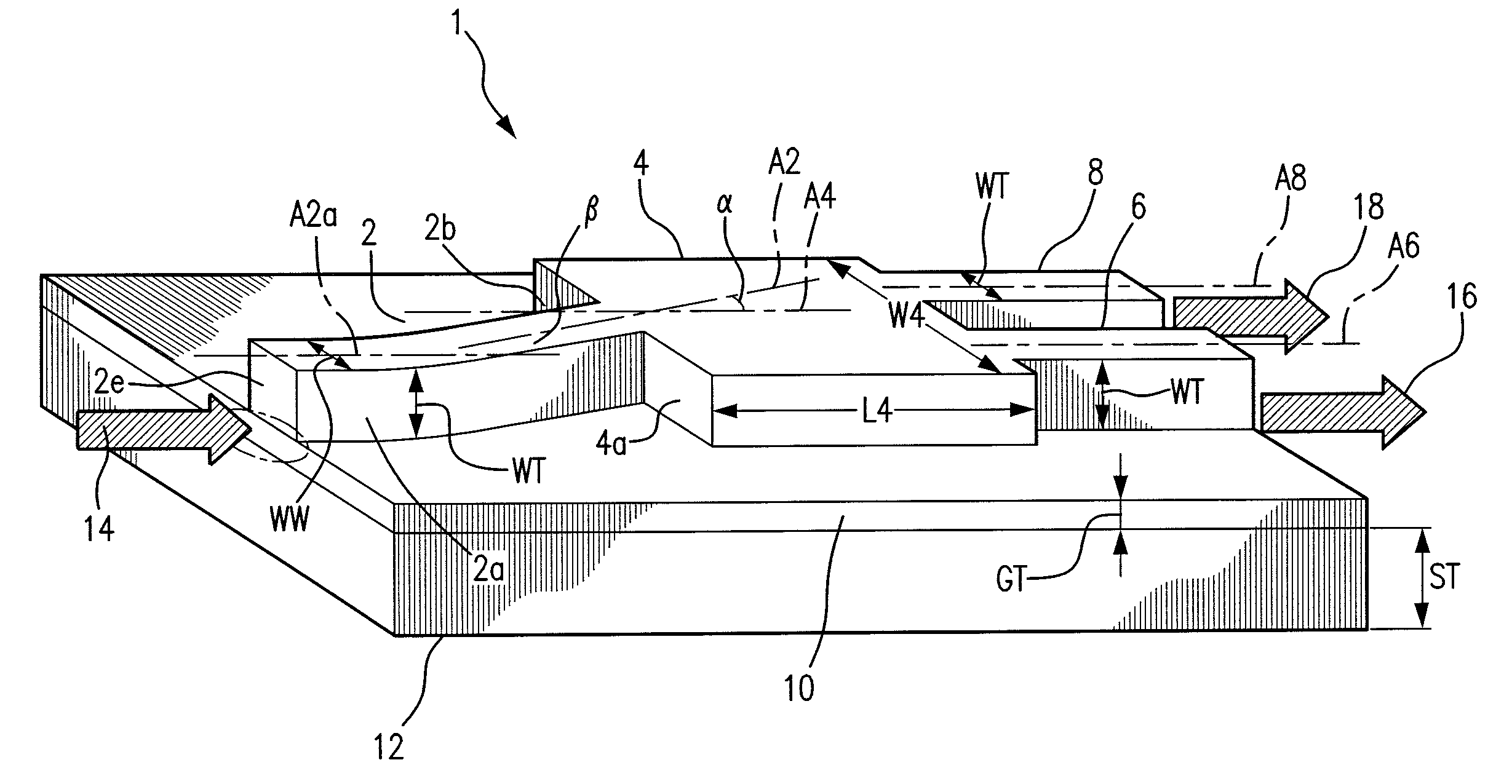
[0017]Integrated optical devices capable of equal 1×N splitting of optical power may include a single mode input waveguide, a multimode section and N single mode output waveguides, where N represents any positive integer. In one embodiment, N may be a multiple of two and for equal splitting the input waveguide is typically centrally located on the input face of the multimode region and the output waveguides are typically evenly spaced along the output face. By selecting the width and length of the multimode section, the light emanating from the input waveguide is “self-imaged” to form N images at the entrances to the output waveguides.

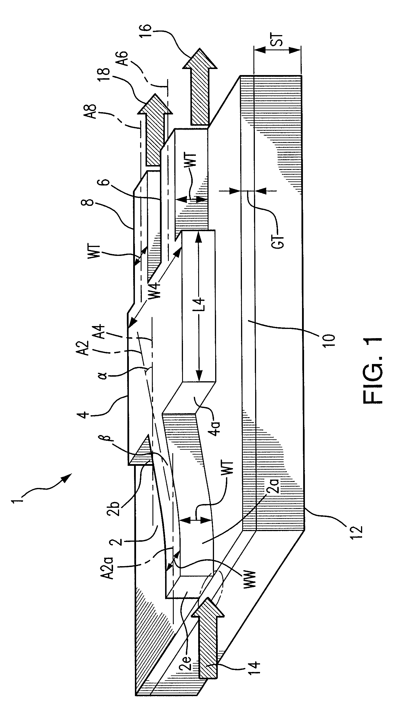
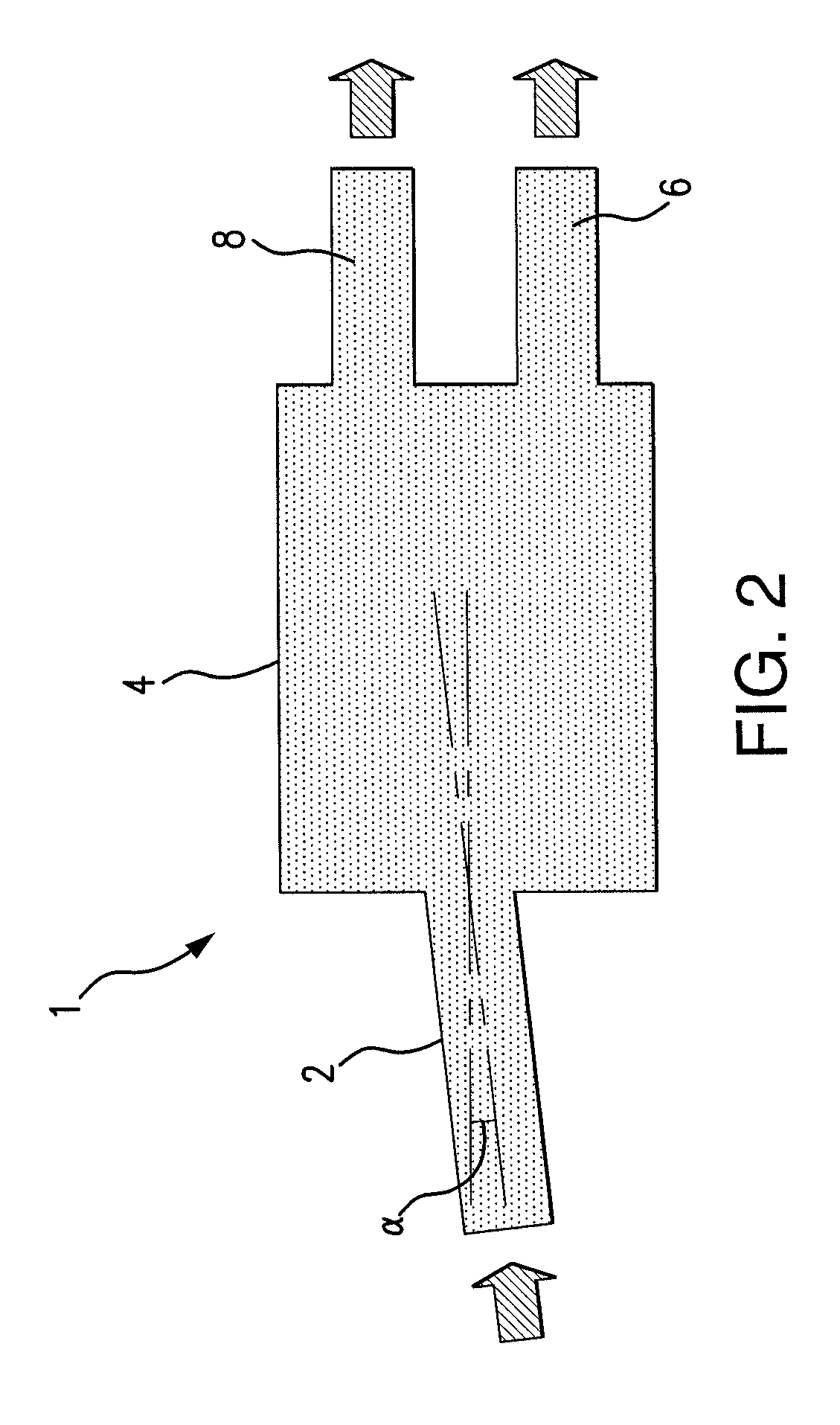
[0018]Various embodiments are directed to a multimode interference (MMI) coupler having an input waveguide, a MMI portion optically coupled at a first end to the input waveguide, and first and second output waveguides optically coupled to a second end of the MMI portion.

[0019]Other embodiments include a method for splitting an optical signal. The metho...


PUM


Abstract

A multimode interference splitter / combiner that includes a monolithic device for photonically coupling an input optical waveguide to first and second output optical waveguides. The input waveguide may be optically coupled to a first end of a MMI portion, while the first and second output waveguides may be optically coupled to a second end of the MMI portion. The input waveguide is coupled to a planar facet of the MMI portion so that the input waveguide may have a propagation axis that is oriented at an angle with respect to the planar facet of the MMI portion. A desired splitting ratio may be achieved by adjusting the angle between the input waveguide and the MMI portion.

Description

FIELD OF THE DISCLOSURE[0001]The disclosure relates generally to the field of optical devices, and more particularly to a multimode interference (MMI) device for performing optical beam splitting and / or combining.BACKGROUND OF THE DISCLOSURE[0002]Multimode interference (MMI) devices, such as MMI couplers, are important integrated optical components for optical signal processing and routing. MMI devices typically utilize direct coupling in which the input waveguide is in contact with one or more output waveguides. This is in contrast to indirect coupling which relies upon evanescent field coupling through waveguides which are in close proximity to each other.[0003]MMI devices may be used for beam splitting, combining and coupling and contain one or more input waveguides and one more output waveguides. Input and output waveguides are connected to a central multimode waveguide region. An MMI device of particular interest consists of one input waveguide and two or more output waveguides...

Claims


Application Information

Patent Timeline
IPC IPC(8): G02B6/26
CPCG02B6/2813G02B6/125
Inventor KWAKERNAAK, MARTIN H.WADA, HIROSHI
Owner NEOPHOTONICS CORP
Learn More