
Banding artifact detection in digital video content

a technology of digital video content and artifact detection, applied in the field of banding artifacts, can solve the problems of degrading visual video quality, unsatisfactory use of human effort to perform the detection task, and low bit depth can easily create banding artifacts

Active Publication Date: 2013-09-10
INTERDIGITAL MADISON PATENT HLDG
View PDF16 Cites 6 Cited by
  • Summary
  • Abstract
  • Description
  • Claims
  • Application Information

AI Technical Summary

Benefits of technology

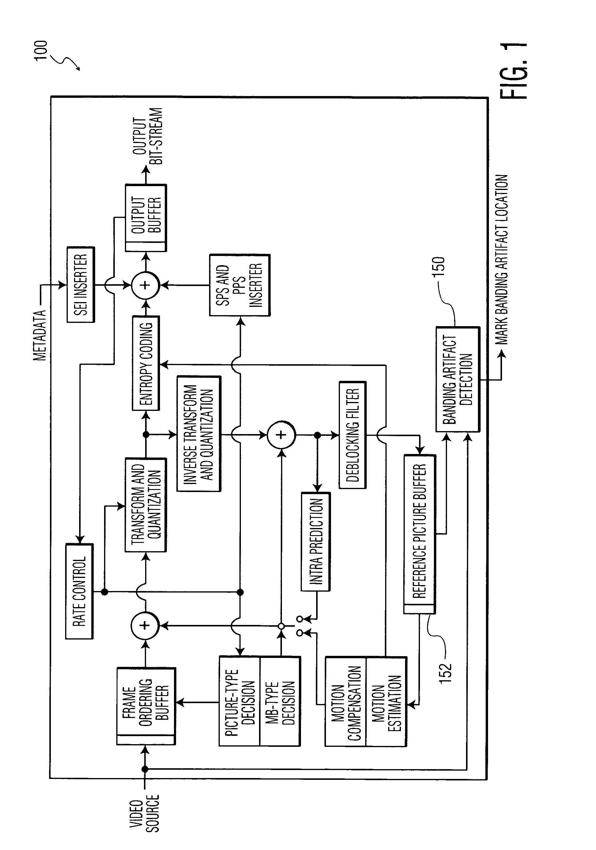
The patent describes a video processing method that detects banding artifacts in digital video content using a mask image created based on global gradient changes and local gradients. The method divides video pictures into blocks, generates a gradient field using an attribute associated with the blocks, and creates a plurality of blobs from elements from the gradient fields. The method also establishes whether an area of the picture corresponding to a blob is an area containing a banding artifact. The video encoder of the patent includes a banding artifact detector to create the mask image and detect banding artifacts in video content. The technical effect is to improve video processing and video quality by detecting and eliminating banding artifacts in video content.

Problems solved by technology

The bit depth conversion from higher to lower bit depth can easily create banding artifacts.
Even though removing redundancy provides a high compression ratio, the visual video quality is degraded with the introduction of artifacts at the decompressed picture.
Using human effort to perform the detection task is not desirable because it consumes a lot of time and energy.
Moreover, human detection of banding artifacts is prone to human errors resulting in missing existing artifacts.
There are not many solutions that consider the detection and correction of banding artifacts in video contents.
However, this method does not take the original video contents into account for determining banding artifacts.
Therefore, such a method can falsely declare banding effect intended by the video producers as banding artifacts.
Then, the application of filters to remove these intended banding negatively affects (or degrades) the quality of the encoded video.

Method used


Image

  • Banding artifact detection in digital video content
  • Banding artifact detection in digital video content
  • Banding artifact detection in digital video content

Examples


Embodiment Construction

[0030]Within the description of the invention, the term large binary object or blob is used to describe an area of a video picture where elements of a video picture such as pixels are touching and of a same logical state. A similar use of blob analysis entails identifying elements of a video picture that form a continuous region based upon a common characteristic for such elements as color, hue, and the like, where the common characteristic can be of a particular range. Such examples of the term blob and of blob analysis are not limited to the recited examples herein and are to be applied consistently with the principles of the present invention.

[0031]Also, the term video picture used herein is to be representative of video information that is from a sequence of moving video pictures. The various techniques described herein for identifying banding artifacts in a video picture can be applied to a video frame, as the terms video frame, video picture, and video image, are used within t...


PUM


Abstract

A method and system for identifying and determining banding artifacts in digital video content composed of a sequence of moving video pictures includes creating a mask image corresponding to a picture from said sequence of moving video pictures based on global gradient changes to detect potential areas containing banding artifacts. The values of the mask image are scaled thereby making banding artifact detection possible using gradient operators. The banding artifacts are then identified / detected based on the local gradients.

Description

CROSS REFERENCES[0001]This application is a National Stage Application and claims the benefit, under 35 U.S.C. §365 of International Application PCT / US2007 / 026035 filed Dec. 19, 2007 which was published in accordance with PCT Article 21(2) on Jul. 17, 2008 in English, and which claims the benefit of U.S. Provisional Patent Application No. 60 / 877,561 filed Dec. 28, 2006.BACKGROUND[0002]1. Technical Field[0003]The principles of the present invention relate to banding artifacts which can be present in digital video.[0004]2. Description of Related Art[0005]Digital video is typically captured or produced at high bit depth (16 bits per component for animated content). However, current video encoders and display devices have been designed to compress signals with 8 bits per component or less. The bit depth conversion from higher to lower bit depth can easily create banding artifacts. That is, banding artifacts are perceived as bands of distinctive colors in what should be a gradual color t...

Claims


Application Information

Patent Timeline
Patent Type & Authority Patents(United States)
IPC IPC(8): H04N7/12H04N11/02H04N11/04
CPCG06T7/403H04N19/86H04N19/17H04N19/154G06T7/44H04N19/85
Inventor KUMWILAISAK, WUTTIPONGDANE, GOKCEGOMILA, CRISTINA
Owner INTERDIGITAL MADISON PATENT HLDG
Learn More