
Three-dimensional object-forming apparatus

a technology of three-dimensional objects and printing apparatuses, which is applied in the direction of manufacturing enclosures, liquid/fluent solid measurements, artificial filament recovery, etc., can solve the problems of reducing affecting the subsequent operation of the printing apparatus, and reducing the efficiency of the printing apparatus. , to achieve the effect of reducing production costs, avoiding construction powder waste, and increasing the capacity of the compartmen

Active Publication Date: 2013-09-03
MICROJET TECH
View PDF12 Cites 21 Cited by
  • Summary
  • Abstract
  • Description
  • Claims
  • Application Information

AI Technical Summary

Benefits of technology

The present invention is a three-dimensional object-forming apparatus that has a tank system to regulate powder application based on different thickness requirements, reducing waste and lowering production costs. The rationing roller has multiple compartments to achieve even powder application and improve powder deficiency. The apparatus also includes a heating device to speed up the adhesive and powder combination, a liquid-supplying device to continuously supply adhesant, a dust-proof device for driving components, and an inkjet-print head maintenance device for complete cleaning and sealing. The technical effects of the invention reduce waste, lower production costs, and improve the efficiency and durability of the three-dimensional object-forming process.

Problems solved by technology

However, the printing heads of the printing apparatus generally used in the rapid prototyping technique are not sealed, when the ink-jet printing process is not being carried out.
The dried adhesive residue may impair the subsequent operation of the printing apparatus, and hence the benefits of the system cannot be ensured.
However, no matter what the mold's size is or how the apparatus is modified, several, even tens of hours are spent to obtain a 3D model.
In addition, when the printing head is blocked and the blocked printing head is not found or determined timely during the process of lamination, significant amounts of time and materials are wasted.
At the instant that the droplets of the printing adhesive adhere to the powder, the nano-sized powder grains not adhered to the droplets may float in the air due to turbulence arising from the high printing rate.
Besides, the conventional apparatus does not comprise a quantitative powder-supplying device, so the remaining powder has to be delivered back into the recycle tank.
During delivering of the remaining powder, the powder may descend inappropriately, causing pollution as well as waste of energy.
Furthermore, excessive time is spent after each powder-spreading step and several hours have to be spent waiting for the completed model to dry.
If the strength of the model is insufficient or the model is not taken out properly, damage may occur thereto.
Only when the model is strong enough, it can be taken out, and this results in inability to achieve the purpose of rapid prototyping.

Method used


Image

  • Three-dimensional object-forming apparatus
  • Three-dimensional object-forming apparatus
  • Three-dimensional object-forming apparatus

Examples


Embodiment Construction

[0040]Several typical embodiments showing the features and advantages of the present invention are explained in relation in the following paragraphs, and it is to be understood that many other possible modifications and variations can be made without departing from the spirit and scope of the invention as hereinafter claimed.

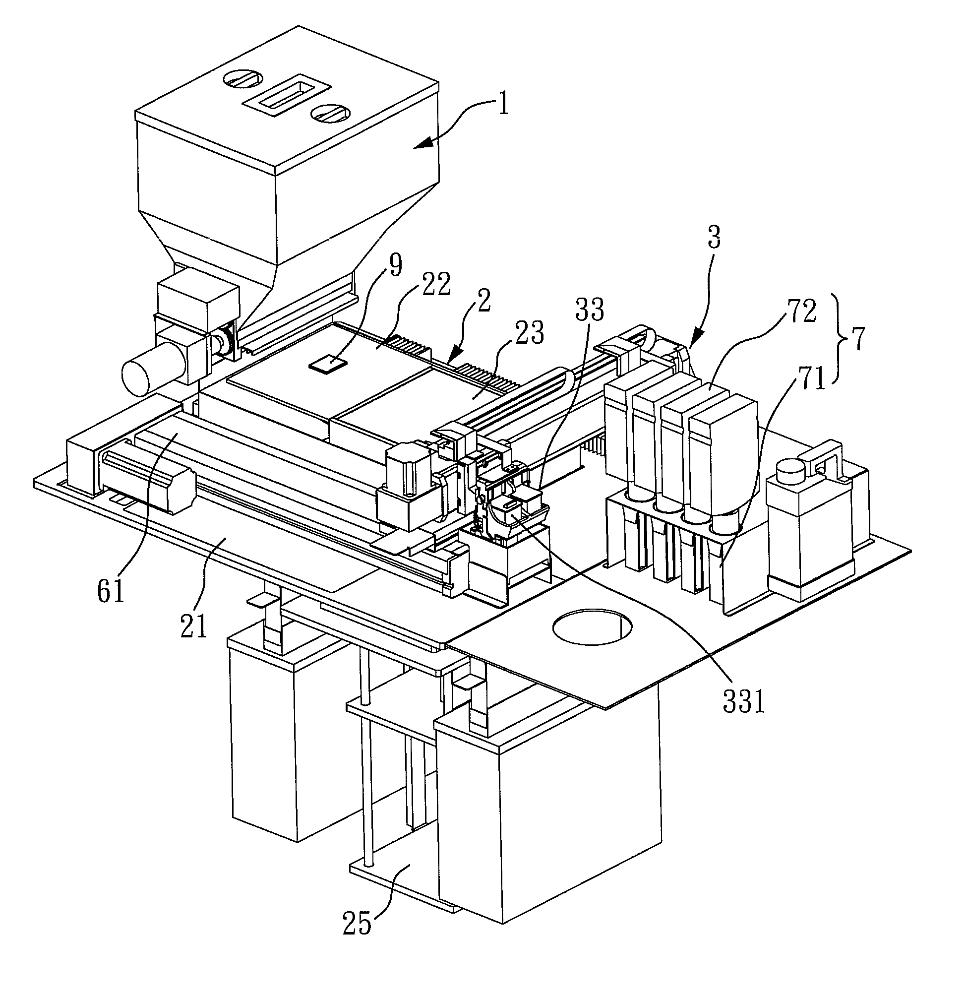
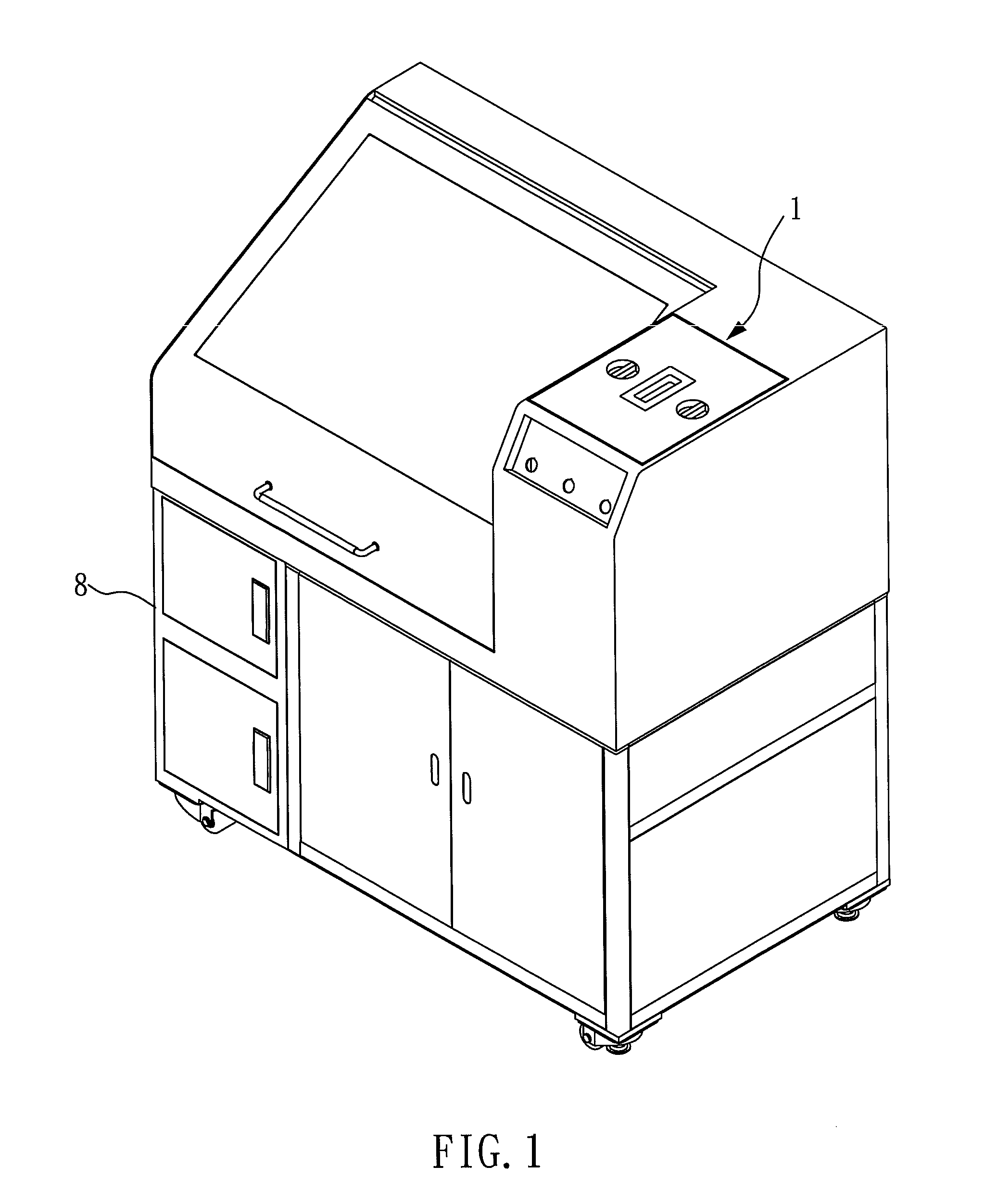
[0041]With reference to FIGS. 1 and 2, they are exterior and interior views of the three-dimensional object-forming apparatus in a preferred example of the present invention. As shown in FIGS. 1 and 2, the three-dimensional object-forming apparatus of the present invention mainly includes an in-batches powder-rationing tank system 1, a construction tank system 2, a printing powder-applying system 3, a rapid drying heating system 4 (shown in FIG. 5C), a printing maintenance device 5 (shown in FIG. 7A), a dust-proof device 6 (shown in FIG. 6), a successive liquid-supplying device 7 (shown in FIG. 8), a powder auto-filtrating and recycling device 8 (shown in FIG. 9...


PUM

PropertyMeasurementUnit
thicknessaaaaaaaaaa
thicknessaaaaaaaaaa
thicknessaaaaaaaaaa

Abstract

A three-dimensional object-forming apparatus is disclosed, which includes an in-batches powder-rationing tank system, a construction tank system, a printing powder-applying system, a rapid drying heating system, a printing maintenance device, a dust-proof device, a successive liquid-supplying device, a powder auto-filtrating and recycling device, and a print quality detection device.

Description

BACKGROUND OF THE INVENTION[0001]1. Field of the Invention[0002]The present invention is relates to a three-dimensional object-forming apparatus.[0003]2. Description of Related Art[0004]Rapid prototyping (RP) is developed according to the concept of a laminating process for forming pyramids. The technical feature of the rapid prototyping is rapid shaping, and transforming designed programs with complex configurations into three-dimensional (3D) models automatically and rapidly without using any cutting tools, molds and fixtures. Hence, the rapid prototyping can greatly reduce the study times and the research costs of new products, and ensure the time-to-market and the first-time success rate of the new products. The rapid prototyping is a more complete and conventional tool of product design for technical personnel to introduce new products to other technical personnel and non-technical personnel such as an enterprise's decision makers and users. Therefore, it is possible to increas...

Claims


Application Information

Patent Timeline
Patent Type & Authority Patents(United States)
IPC IPC(8): B28B17/00
CPCB29C67/0081B29C67/0085B29C64/165B33Y30/00B33Y40/00B29C64/255B29C64/343B29C64/329
Inventor TUNG, YA CHINGSHI, KWO YUAN
Owner MICROJET TECH
Learn More