
Simplified direct-reading porosity measurement apparatus and method

a porosity measurement and direct numerical technology, applied in the direction of vibration measurement in solids, analysis of fluids using sonic/ultrasonic/infrasonic waves, instruments, etc., can solve the problems of high cost of producing and transporting porosity standards for porosity measurement purposes, significant challenges for laminate composite materials, and variability in measurement of porosity

Active Publication Date: 2013-09-03
THE BOEING CO
View PDF10 Cites 16 Cited by
  • Summary
  • Abstract
  • Description
  • Claims
  • Application Information

AI Technical Summary

Benefits of technology

The patent describes a diagnostic apparatus for measuring the porosity of a structure using ultrasonic waves. The apparatus includes an ultrasonic transducer device that emits ultrasonic pulses into the structure and detects echo profiles. An electronic device processes the ultrasonic signals and a display shows the results as a porosity indicator. The method involves transmitting an ultrasonic signal into the structure, receiving the response, filtering the signals, obtaining a reference amplitude, measuring the amplitude variation, and calculating the porosity level based on the measured attenuation of the ultrasonic signal. This invention provides a non-destructive and accurate method for measuring porosity of structures.

Problems solved by technology

Assessments of laminate composite materials represent significant challenges with regard to efficiencies in time, cost, and training Factory workers and ground maintenance crews often must use highly sophisticated techniques to make assessments of defective areas.
The main cause of measurement variability in porosity is the varying high and low frequency content or bandwidth of different sensors and electronic receivers used across the industry.
However, the cost of producing and transporting porosity standards for porosity measurement purposes may be excessive.

Method used


Image

  • Simplified direct-reading porosity measurement apparatus and method
  • Simplified direct-reading porosity measurement apparatus and method
  • Simplified direct-reading porosity measurement apparatus and method

Examples


Embodiment Construction

[0018]The present disclosure now will be described more fully hereinafter with reference to the accompanying drawings, in which some, but not all embodiments of the disclosure are shown. Indeed, the disclosure may be embodied in many different forms and should not be construed as limited to the embodiments set forth herein; rather, these embodiments are provided so that this disclosure will satisfy applicable legal requirements. Like numbers refer to like elements throughout.

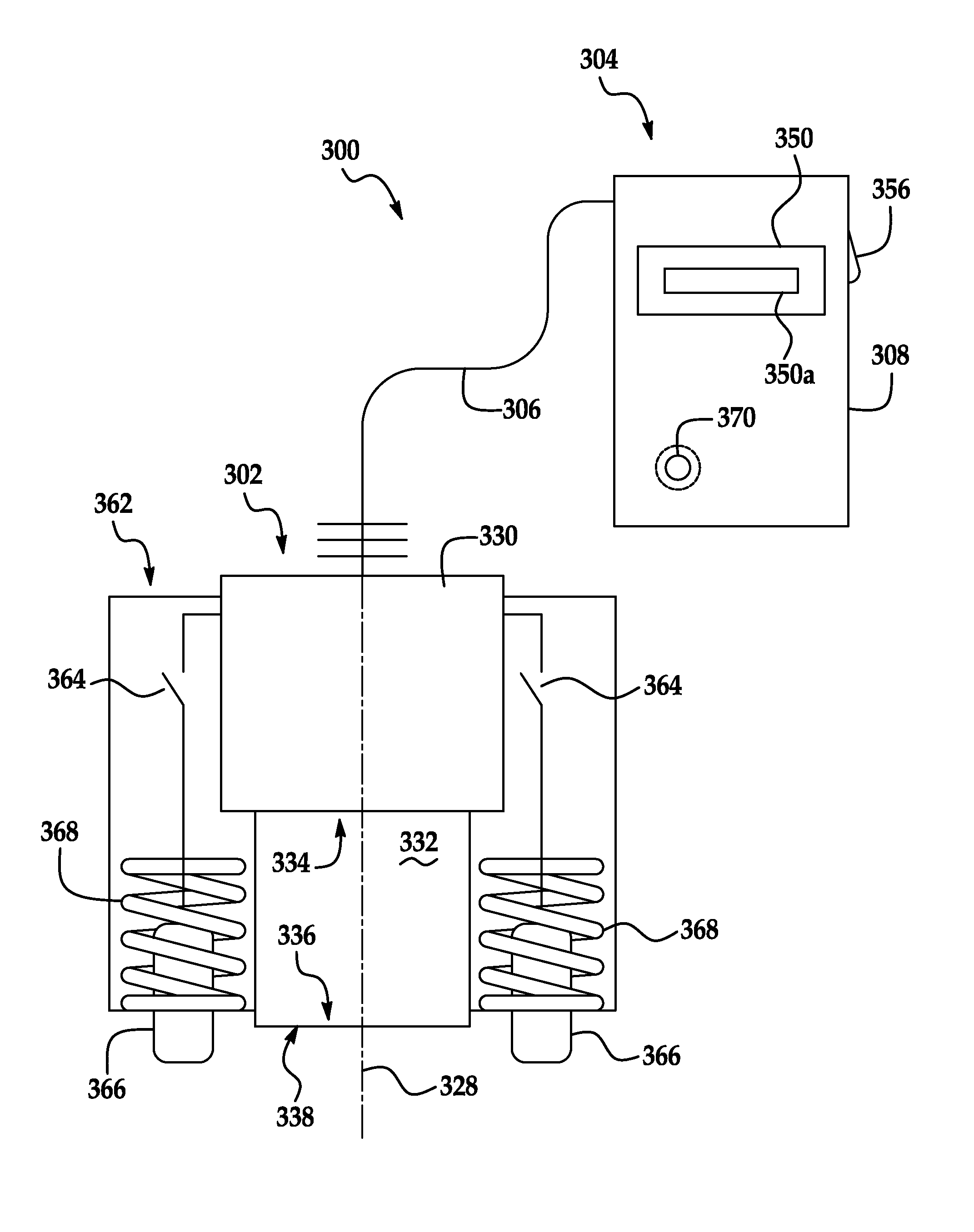
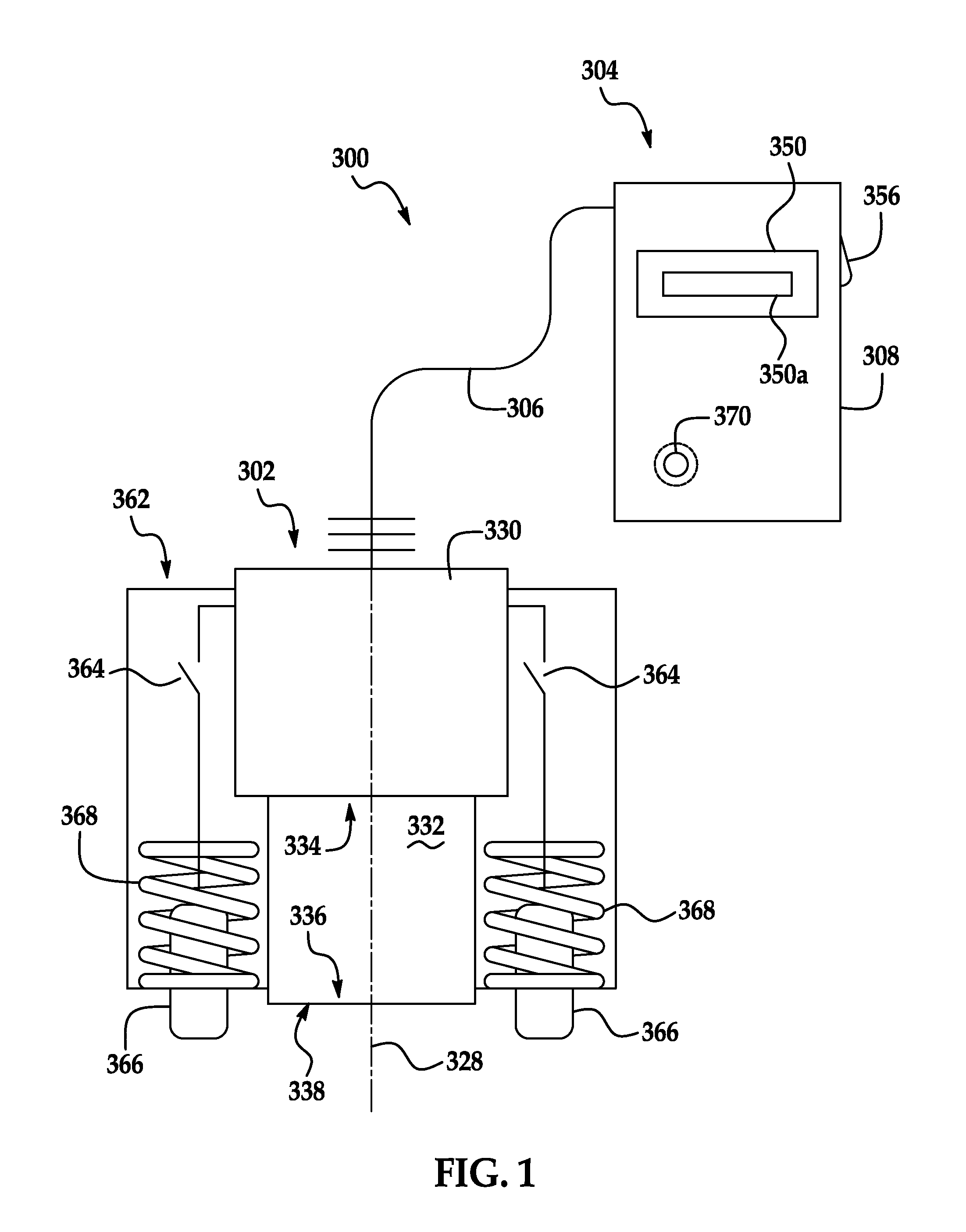
[0019]FIG. 1 illustrates a direct-reading porosity measurement apparatus, hereinafter apparatus, according to an embodiment of the present disclosure. The apparatus 300 may include an ultrasonic transducer device 302 and an electronic device 304 having a housing 308, a display 350, a powerswitch 356, and a hidden calibration activator 370. The embodiment of the display 350 illustrated in FIG. 1 may include a porosity indicator 350a for indicating the percent porosity of a structure which is measured using the ap...


PUM


Abstract

An apparatus for measuring porosity of a structure includes an ultrasonic transducer device configured to be pressed against a structure, the ultrasonic transducer device being further configured to emit ultrasonic pulses into the structure and detect echo profiles; and an electronic device including: a manager having an interface gate, a back-surface sensing gate and a back surface analysis gate; a pulse generator interfacing with the manager and the ultrasonic transducer device; a data acquisition device interfacing with the ultrasonic transducer device and the manager; and a display having a porosity indicator interfacing with the manager.

Description

TECHNICAL FIELD[0001]Embodiments of the present disclosure relate generally to ultrasonic inspections of structures. More particularly, embodiments of the disclosure relate to apparatuses and methods for the direct numerical reading of the porosity of structures.BACKGROUND OF THE DISCLOSURE[0002]Laminate composite materials are becoming increasingly common in the construction of large aircraft. Typical laminate composite materials are composed of layered resin-bonded graphite textiles. Assessments of laminate composite materials represent significant challenges with regard to efficiencies in time, cost, and training Factory workers and ground maintenance crews often must use highly sophisticated techniques to make assessments of defective areas.[0003]In manufacture or repair of laminate composite materials, it is often necessary to measure the porosity of the materials to determine if the structure meets engineering requirements. Porosity, quantified by void area over total unit are...

Claims


Application Information

Patent Timeline
IPC IPC(8): G01N29/036
CPCG01N29/11G01N29/30G01N29/348G01N2291/0289G01N2291/044
Inventor BRADY, STEVEN K.MOTZER, WILLIAM P.KOLLGAARD, JEFFREY R.SMITH, NATHAN R.WOOD, NANCYFORTNER, DAVID
Owner THE BOEING CO
Learn More