Method and system to diagnose exhaust gas sensor deterioration

a technology of exhaust gas sensor and exhaust gas sensor, which is applied in the direction of instruments, structural/machine measurement, material analysis, etc., can solve the problems of increasing the method cannot use fixed gain and frequency, and the adjustment of the sensor can be incorrect, so as to reduce the number of times such analysis is interrupted, detect the deterioration of the exhaust gas sensor, and reduce the number of output cycles

Inactive Publication Date: 2013-08-13
TOYOTA MOTOR CO LTD
View PDF25 Cites 7 Cited by
  • Summary
  • Abstract
  • Description
  • Claims
  • Application Information

AI Technical Summary

Benefits of technology

[0011]Advantageously, the processor detects the deterioration of the exhaust gas sensor using less output cycles, reducing the number of times that such analysis is interrupted. In addition, the processor can determine exhaust gas sensor deterioration for not just the overall operations of the exhaust gas sensor, but also separately for the lean to rich fuel operation and the rich to lean fuel operation.

Problems solved by technology

Such adjustments, however, can be incorrect when the exhaust gas sensor malfunctions due to deterioration.
However, such methods cannot use fixed gain and fixed frequency because the air-fuel ratio data may not cross the necessary thresholds as the sensor response slows.
Furthermore, governmental agencies are increasingly demanding that malfunctions be detected not just for the overall operations of the exhaust gas sensor, but in a more finite manner, such as during lean to rich fuel operations or rich to lean fuel operations.
Conventional methods, however, are unable to parse the malfunctions in such a manner.
With the large number of cycles, there is an increased chance that the method will be interrupted due to a change in automobile speed.
This reduces the amount of tests that can be performed and / or increases the number of attempts that must be made in order to diagnose the exhaust gas sensor deterioration, both of which are undesirable.

Method used


Image

  • Method and system to diagnose exhaust gas sensor deterioration
  • Method and system to diagnose exhaust gas sensor deterioration
  • Method and system to diagnose exhaust gas sensor deterioration

Examples


Embodiment Construction

[0021]Apparatus, systems and methods that implement the embodiments of the various features of the present invention will now be described with reference to the drawings. The drawings and the associated descriptions are provided to illustrate some embodiments of the present invention and not to limit the scope of the present invention. Throughout the drawings, reference numbers are re-used to indicate correspondence between referenced elements.

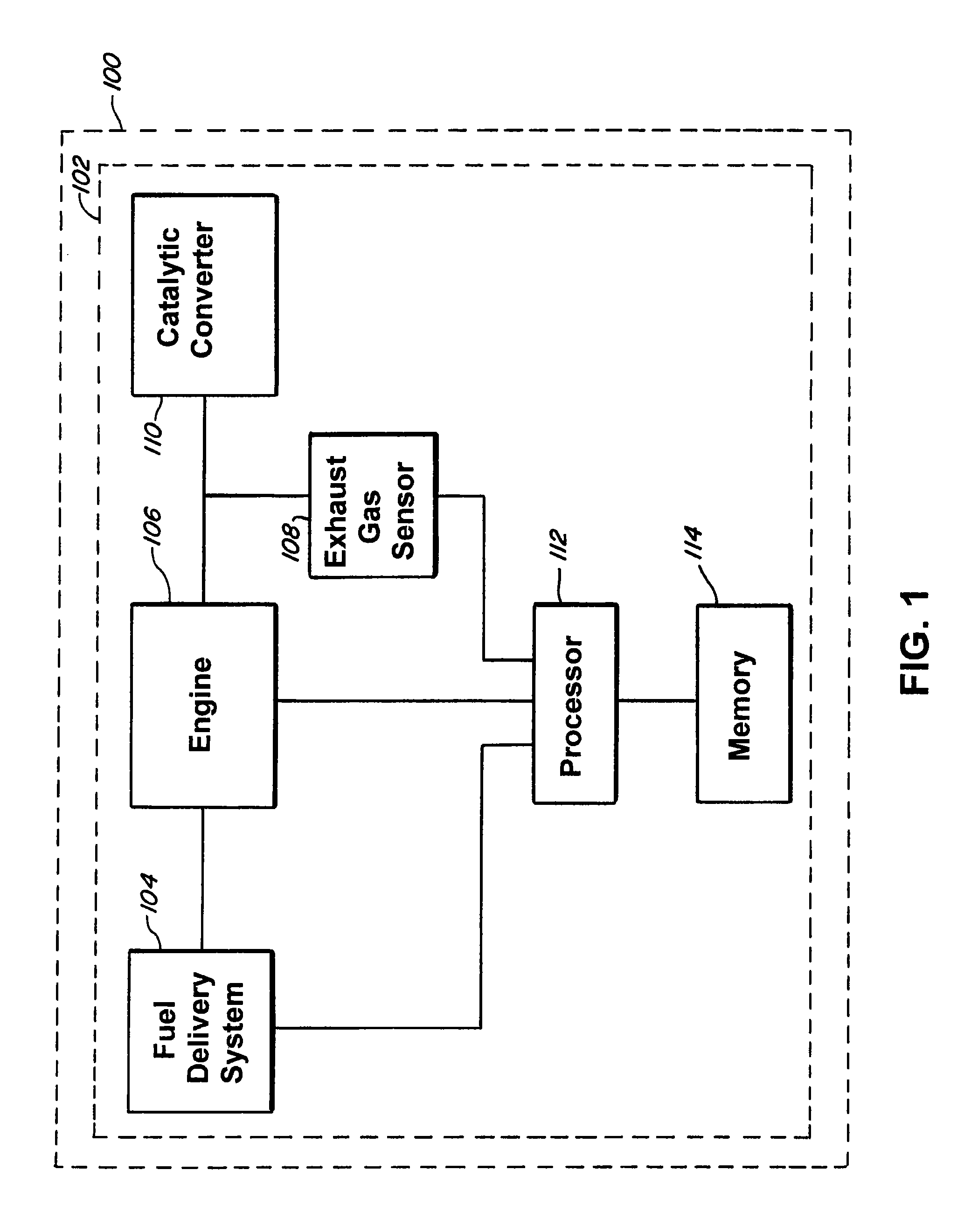
[0022]In one embodiment, the present invention includes an automobile 100. The automobile 100 can include, for example, an exhaust system 102. The exhaust system 102 can include, for example, a fuel delivery system 104, an engine 106, an exhaust gas sensor 108, a catalytic converter 110, a processor 112, and / or a memory 114.

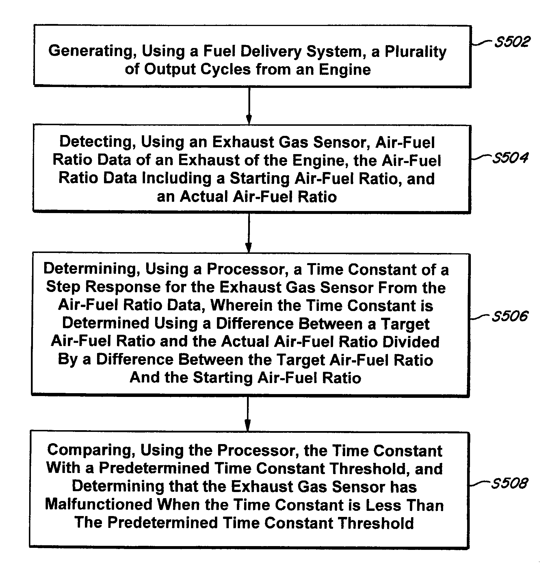
[0023]The fuel delivery system 104 is connected, for example, to the engine 106 and / or the processor 112. The fuel delivery system 104 can control, for example, an amount of fuel delivered to the engine 106. The amount of f...


PUM


Abstract

In a method and system to diagnose exhaust gas sensor deterioration, an automobile includes an exhaust gas system. The exhaust gas system has a fuel delivery system, an engine, a catalytic converter, an exhaust gas sensor, a processor, and / or a memory. The fuel delivery system supplies fuel which is combined with air to form a mixture combusted by the engine to generate exhaust. The processor controls the air-fuel ratio of the mixture based on the air-fuel ratio data of the exhaust detected by the exhaust gas sensor. The catalytic converter reduces pollutants in the exhaust. The processor analyzes the air-fuel ratio data to determine one or more time constants of a step response for rich to lean fuel operations and / or lean to rich fuel operations. The processor compares the time constants to a predetermined time constant threshold to determine if the exhaust gas sensor has malfunctioned.

Description

BACKGROUND[0001]1. Field[0002]The present invention relates to a method and system to diagnose exhaust gas sensor deterioration.[0003]2. Description of the Related Art[0004]A conventional automobile includes an engine which combusts a mixture to generate an exhaust. The composition of the exhaust is regulated by governmental agencies for pollutants. To reduce the amount of pollutants, the air-fuel ratio of the mixture can be controlled. The conventional automobile utilizes an exhaust gas sensor to determine air-fuel ratio data for an exhaust of an engine. Such air-fuel ratio data can determine adjustments to the air-fuel ratio of a mixture supplied to the engine. Such adjustments, however, can be incorrect when the exhaust gas sensor malfunctions due to deterioration.[0005]Conventional methods to detect exhaust gas sensor malfunctions have utilized threshold switching based on the air-fuel ratio data. However, such methods cannot use fixed gain and fixed frequency because the air-fu...

Claims


Application Information

Patent Timeline
Patent Type & Authority Patents(United States)
IPC IPC(8): G01M15/10
CPCG01M15/102G01N1/2252G01N27/4175
Inventor MILLER, RYAN A.
Owner TOYOTA MOTOR CO LTD
Why Eureka
Try Eureka