Optical tomographic image generating apparatus and optical tomographic image generating method
a tomographic image and generating apparatus technology, applied in the field of optical tomographic image generating apparatus and optical tomographic image generating method, can solve the problem of limited image quality enhancement, and achieve the effect of efficiently removing noise components and improving image quality
- Summary
- Abstract
- Description
- Claims
- Application Information
AI Technical Summary
Benefits of technology
Problems solved by technology
Method used
Image
Examples
example 1
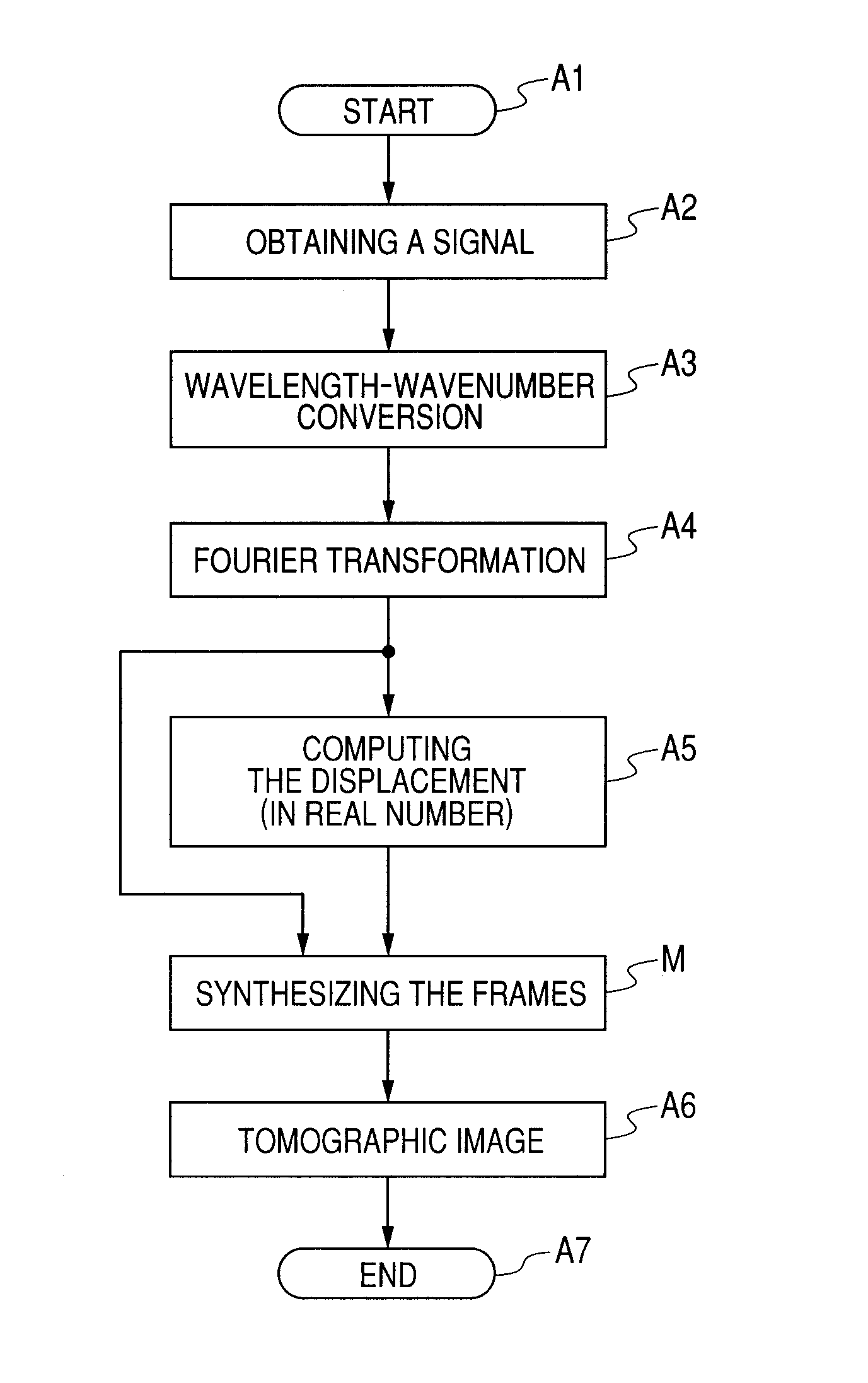
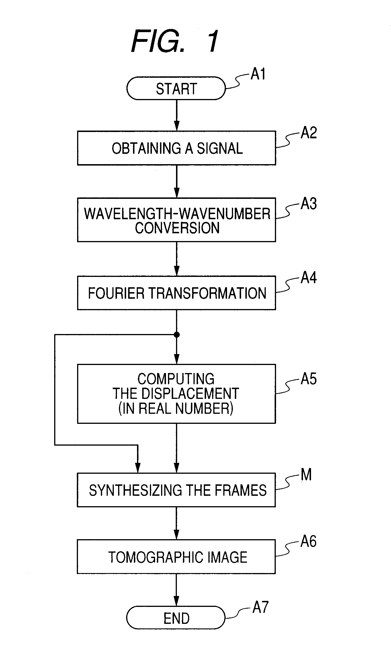
[0020]Next, Example 1 of the present invention will be described. Although in the present example a tomographic image is generated by an imaging apparatus using a Michelson interferometer, an imaging apparatus that can be used for the present invention is not limited to this apparatus, and any type of interferometer, such as a Mach-Zehnder interferometer, for example, can be employed. Also, in the signal processing in the present example, a displacement computation is performed based on real number data, which is different from Example 2 described later.
[0021](Michelson Interferometer)
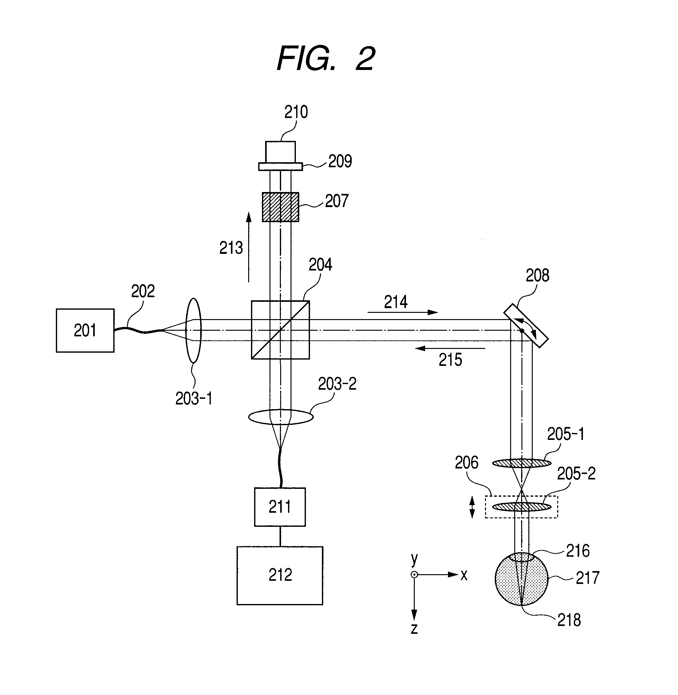
[0022]An optical coherence tomographic imaging apparatus according to Example 1 will be described with reference to FIG. 2. FIG. 2 is a schematic diagram illustrating an imaging apparatus using a Michelson-type optical system (Michelson interferometer) according to the present example.
[0023]A light beam emitted from a light source 201, which is transmitted through a fiber 202 and a lens 203-1, is divid...
example 2
[0055]Next, Example 2 of the present invention will be described. Here, the description will be given especially for differences from Example 1. In the present example, a tomographic image is generated by means of an imaging apparatus using a Mach-Zehnder interferometer. However, an imaging apparatus that can be used in the present invention is not limited to this interferometer, and for example, any interferometer, such as a Michelson interferometer, can be employed. Also, signal processing in the present example includes synthesizing signals of a frame in the frame, and computing a displacement including phase components. Although a mode including both of these features will be described below, the present invention is not limited to the below description, and the present invention may be applied to a mode including only one of the features.
[0056](Mach-Zehnder Interferometer)
[0057]An imaging apparatus using an optical coherence tomographic method according to Example 2 will be des...
example 3
[0074]Also, the present invention can be practiced by performing the following processing. In other words, software (computer program) providing the functions provided by the above-described embodiments is supplied to a system or an apparatus via a network or a recording medium of various types, and a computer (or a CPU or MPU or the like) in the system or the apparatus reads and executes the program.
[0075]In other words, the computer program includes obtaining signals for a plurality of frames by applying a light beam to an object; obtaining respective complex number data by performing Fourier transformation of the signals for the plurality of frames; synthesizing the plurality of frames in complex number form using the respective complex number data; and generating a tomographic image based on the synthesized data. Furthermore, the computer program may further include obtaining frame displacement information, and synthesizing signals for a frame within the frame.
Other Embodiments
[...
PUM
 Abstract
Description
Claims
Application Information
 - R&D
- Intellectual Property
- Life Sciences
- Materials
- Tech Scout
- Unparalleled Data Quality
- Higher Quality Content
- 60% Fewer Hallucinations
Browse by: Latest US Patents, China's latest patents, Technical Efficacy Thesaurus, Application Domain, Technology Topic, Popular Technical Reports.
© 2025 PatSnap. All rights reserved.Legal|Privacy policy|Modern Slavery Act Transparency Statement|Sitemap|About US| Contact US: help@patsnap.com


