
Fiber active path length synchronization

a fiber active path and fiber technology, applied in the direction of fibre transmission, laser details, electrical equipment, etc., can solve the problems of limited output power of narrow linewidth fiber amplifiers, limited active coherent beam combinations, and limited power available from single-mode optical fibers. achieve the effect of reducing sbs, increasing power available, and reducing sbs

Inactive Publication Date: 2013-08-06
THE UNITED STATES OF AMERICA AS REPRESETNED BY THE SEC OF THE AIR FORCE
View PDF15 Cites 18 Cited by
  • Summary
  • Abstract
  • Description
  • Claims
  • Application Information

AI Technical Summary

Benefits of technology

One way to increase the power available through a system is to broaden the linewidth of the master oscillator, which increases the threshold for a certain non-linear effect. This allows for coherent beam combination of output power from multiple fibers, resulting in higher overall power output. However, this method requires highly accurate path length matching between the amplifiers. The present invention introduces a novel all-fiber method for path length matching that enables this matching between the amplifiers. This results in increased power output from each fiber in the system.

Problems solved by technology

The intensity and, hence, the power available from a single-mode optical fiber is limited by either optical surface damage or nonlinear optical effects.
However, this is not a necessary condition for achieving accurate phase control.
The output power of a narrow linewidth fiber amplifier is limited by Stimulated Brillouin Scattering (SBS).
While this is an effective technique for mitigating SBS it presents problems for active coherent beam combination since the coherence length is inversely proportional to the linewidth and decreases as the linewidth increases.
However, this is not a necessary condition for achieving accurate phase control.
However, mechanical optical trombones are devices that are vibration sensitive and therefore require very rigid and expensive vibration isolation systems.
Mechanical sensitivity may make these systems unsuitable for many potential applications.
While this sounds straight forward it is difficult to do with current fiber fusing technology because the fiber length added can generally be controlled only to an accuracy of a few centimeters due to uncertainty in the quality of the fiber cleaving and fusing processes.
Thus this approach is not suitable for path length matching of a large number of broad linewidth optical fibers since the optical paths must be matched to within less than the coherence length which may be quite small.
However, these devices have two problems, first they are microphonic as well as vibration sensitive and second their dynamic range is generally limited to small changes in the path length.
This, however, incurs the added penalty of requiring accurate path length matching systems.
Because vibration sensitivity is an issue for some applications, some forms of path length matching will be unsuitable.
The power available from a single-mode optical fiber is limited by either optical surface damage or nonlinear optical effects.
The primary limitation on the output power of a narrow linewidth optical fiber is the nonlinear optical effect of Stimulated Brillouin Scattering (SBS).

Method used


Image

  • Fiber active path length synchronization
  • Fiber active path length synchronization
  • Fiber active path length synchronization

Examples


Embodiment Construction

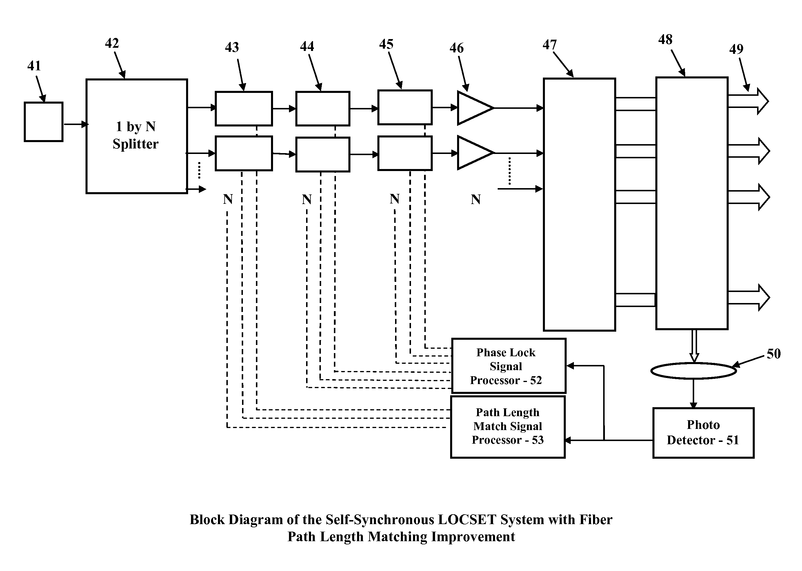
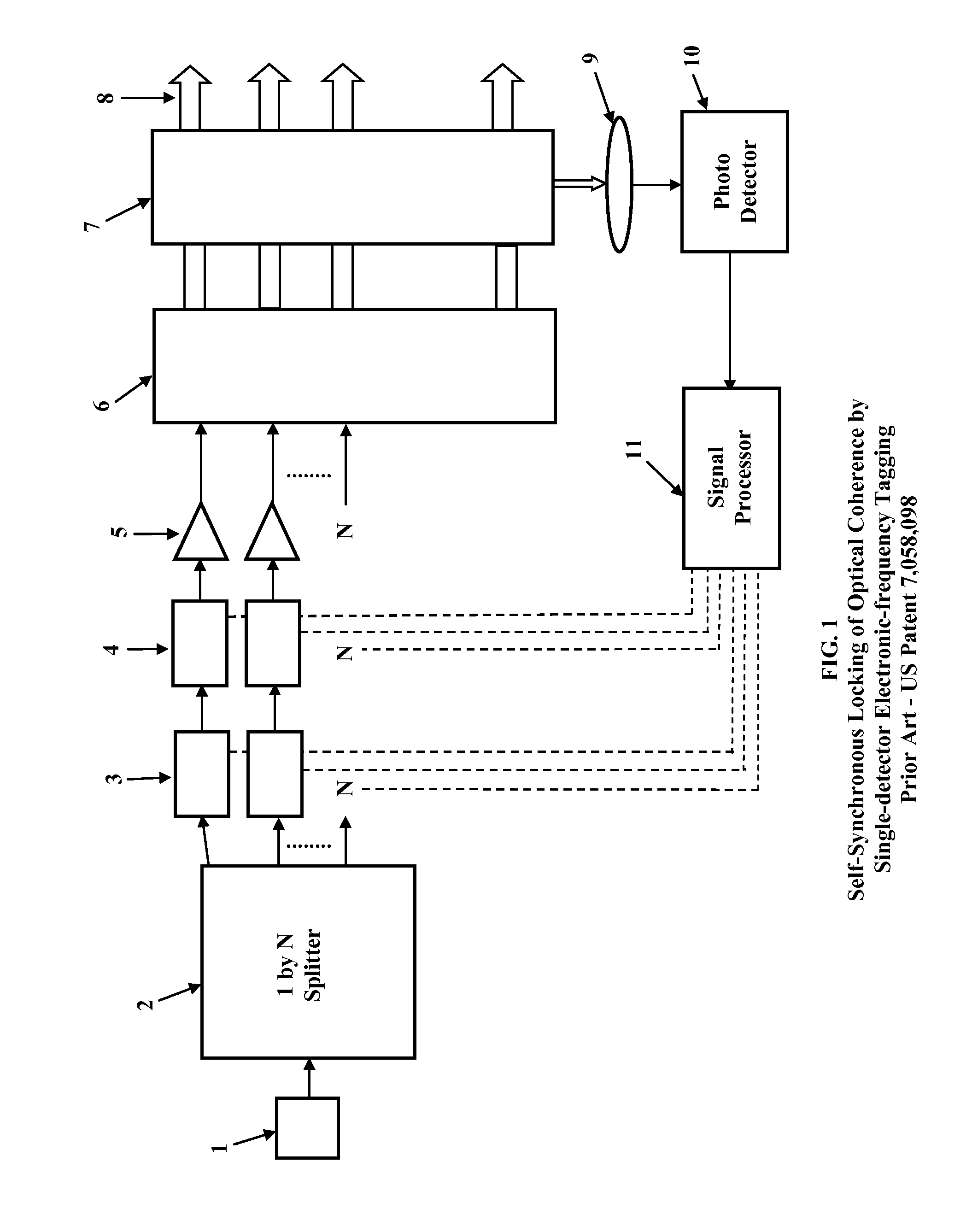
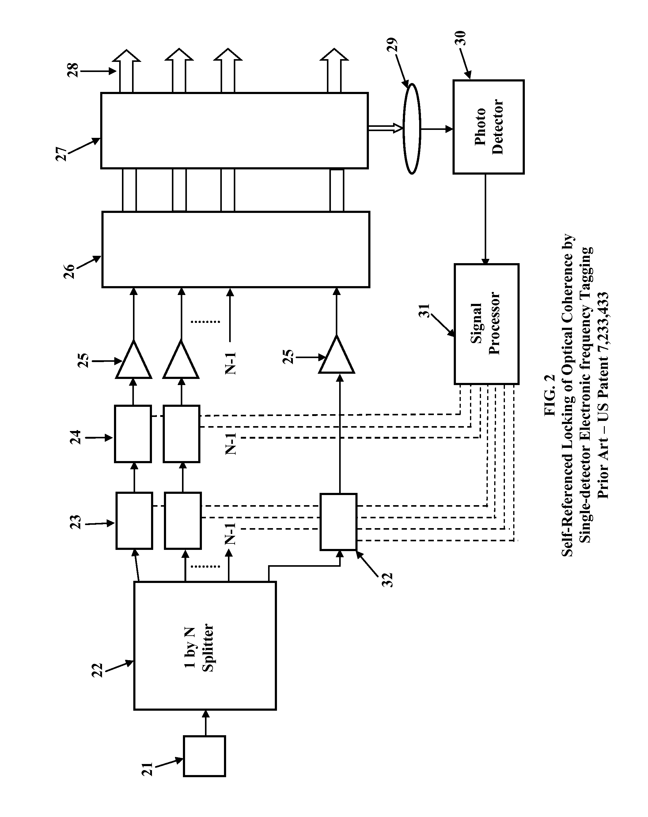
[0029]Self-Synchronous LOCSET system with the fiber path length matching improvement In the embodiment for Self-Synchronous LOCSET with the fiber path length matching improvement, N fiber amplifier legs are adjusted for both optical phase and path length matching. A block diagram for this embodiment of the present invention is shown in FIG. 3. The first device in the diagram is a master oscillator laser 41 having a linewidth greater than the SBS linewidth. The output power from the master oscillator is divided by a 1×N power splitter 42. Each of the N output signals from the 1×N power splitter 42 are then directed to N temperature controlled spools of passive optical fiber 43 where the temperature of each of the N fiber spools is adjusted to match the optical path length of the array elements. Each of the N output signals from the N temperature controlled spools of passive optical fiber 43 are then directed to N optical modulators 44 where each of the N signals is modulated by a uni...


PUM


Abstract

A method of implementing a high-power coherent laser beam combining system in which the output of a master oscillator laser having a linewidth broader than the Stimulated Brillouin Scattering linewidth of the laser signal is split into N signals and fed into an array of N optical fibers. This is a modification of the self-synchronous LOCSET and self-referenced LOCSET phase matching systems in which the optical path length of each optical fiber is matched to less than the signal coherence length of the master oscillator by using a path length matching signal processor to modulate temperature controlled segments of each optical fiber.

Description

STATEMENT OF GOVERNMENT INTEREST[0001]The conditions under which this invention was made are such as to entitle the Government of the United States under paragraph 1(a) of Executive Order 10096, as represented by the Secretary of the Air Force, to the entire right, title and interest therein, including foreign rights.BACKGROUND OF THE INVENTION[0002]The present invention relates generally to multiple element optical amplifier arrays used to achieve a high output power laser beam and in particular, to a system to enable coherent beam combination of laser amplifier arrays.[0003]The intensity and, hence, the power available from a single-mode optical fiber is limited by either optical surface damage or nonlinear optical effects. The limitations to achieving a high power fiber laser system can be overcome by coherent beam combination of the output power from multiple, broader linewidth optical fiber amplifiers. In a master oscillator power amplifier (MOPA) configuration having multiple ...

Claims


Application Information

Patent Timeline
Patent Type & Authority Patents(United States)
IPC IPC(8): H01S3/00
CPCH01S3/2383H01S3/1307H01S3/06754
Inventor HENRY, LEANNE J.SHAY, THOMAS M.
Owner THE UNITED STATES OF AMERICA AS REPRESETNED BY THE SEC OF THE AIR FORCE
Learn More