
Systems and methods for installing ankle replacement prostheses

a technology for ankle replacement and system, applied in the field of systems and ankle replacement prostheses, can solve the problems of increasing the cost of surgery, increasing the number of surgical procedures, and fewer satisfactory options, and achieve the effect of reducing the occurrence of subsidence and aseptic loosening

Inactive Publication Date: 2013-07-30
INBONE TECH
View PDF9 Cites 30 Cited by
  • Summary
  • Abstract
  • Description
  • Claims
  • Application Information

AI Technical Summary

Benefits of technology

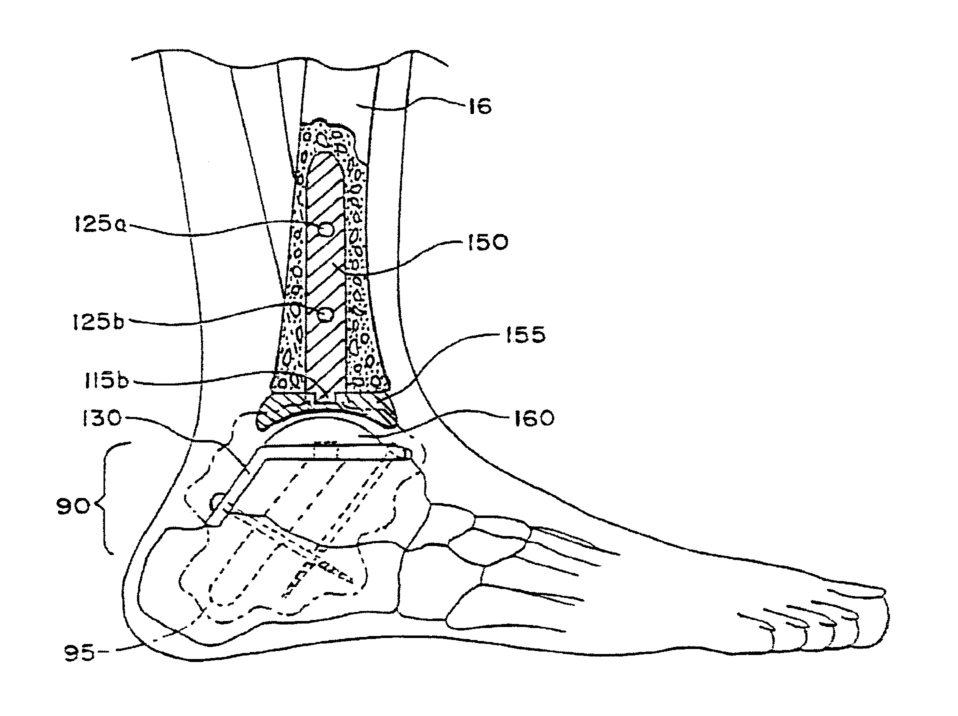
This patent describes a new implant for ankle replacement surgery that solves issues with current methods. The implant includes a femoral component, a bearing component, and a talar component. The talar component can be interchanged with another talar component, and the method involves preparing the talar and tibial cavities and selecting the desired mounting components for the talus. The invention improves the stability and flexibility of ankle replacement surgery.

Problems solved by technology

Until the early to mid 1970's, patients with injured or diseased ankle joints commonly resulting from osteoarthritis (age-related wear of the joints), or rheumatoid arthritis (generalized joint inflammation causing destructive changes), or traumatic arthritis (damage to a joint from a direct injury), had few satisfactory options when their ankle joints failed.
Many of the prior art surgical procedures were riddled with problems for the patient.
While early success was realized, there was a high long-term term failure rate due to complications such as infection, loosening, and collapse, which lead to additional extensive surgical procedures.
This contributes to aseptic loosening and migration of the device.
Such procedures subsequently require complicated extramedullary realignment and reattachment of the foot.
These procedures commonly result in infection and extended healing time with possible replacement failure from improper extramedullary realignment.
The surgery also has increased risks associated with cutting or damaging neighboring nerves and tendons which may lead to further complications.

Method used


Image

  • Systems and methods for installing ankle replacement prostheses
  • Systems and methods for installing ankle replacement prostheses
  • Systems and methods for installing ankle replacement prostheses

Examples


Embodiment Construction

I. Anatomy of the Ankle

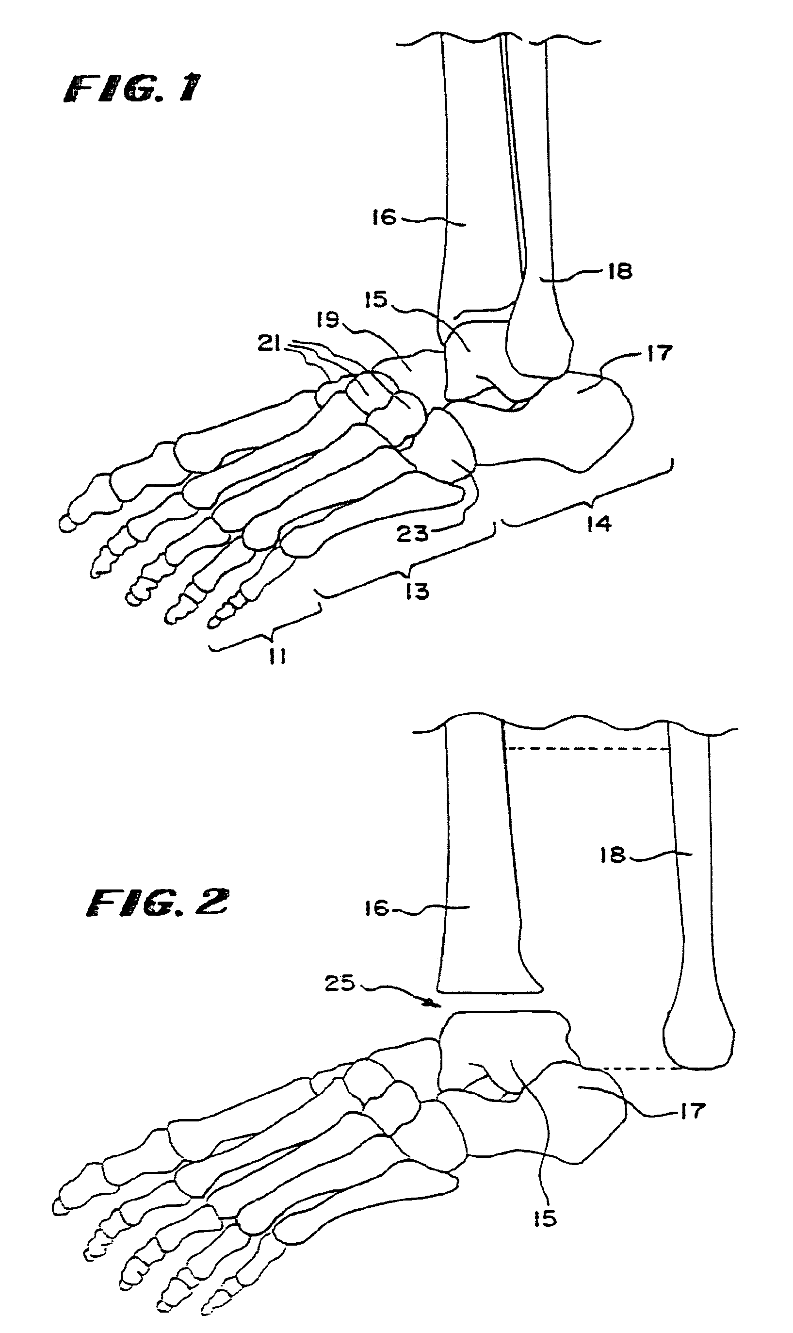
[0036]Referring to FIG. 1, the foot comprises fourteen phalanges or toe bones 11 connected to the metatarsus bones 13. There are also seven tarsal bones 14, of which the talus 15 supports the tibia 16 and the fibula 18, and the heel bone or calcaneus 17. Of the tarsal bones, the talus 15 and the calcaneus 17 are the largest and are adjacent to each other. The other tarsal bones include the navicular 19, three cuneiforms 21, and the cuboid 23.

II. Intramedullary Guidance System

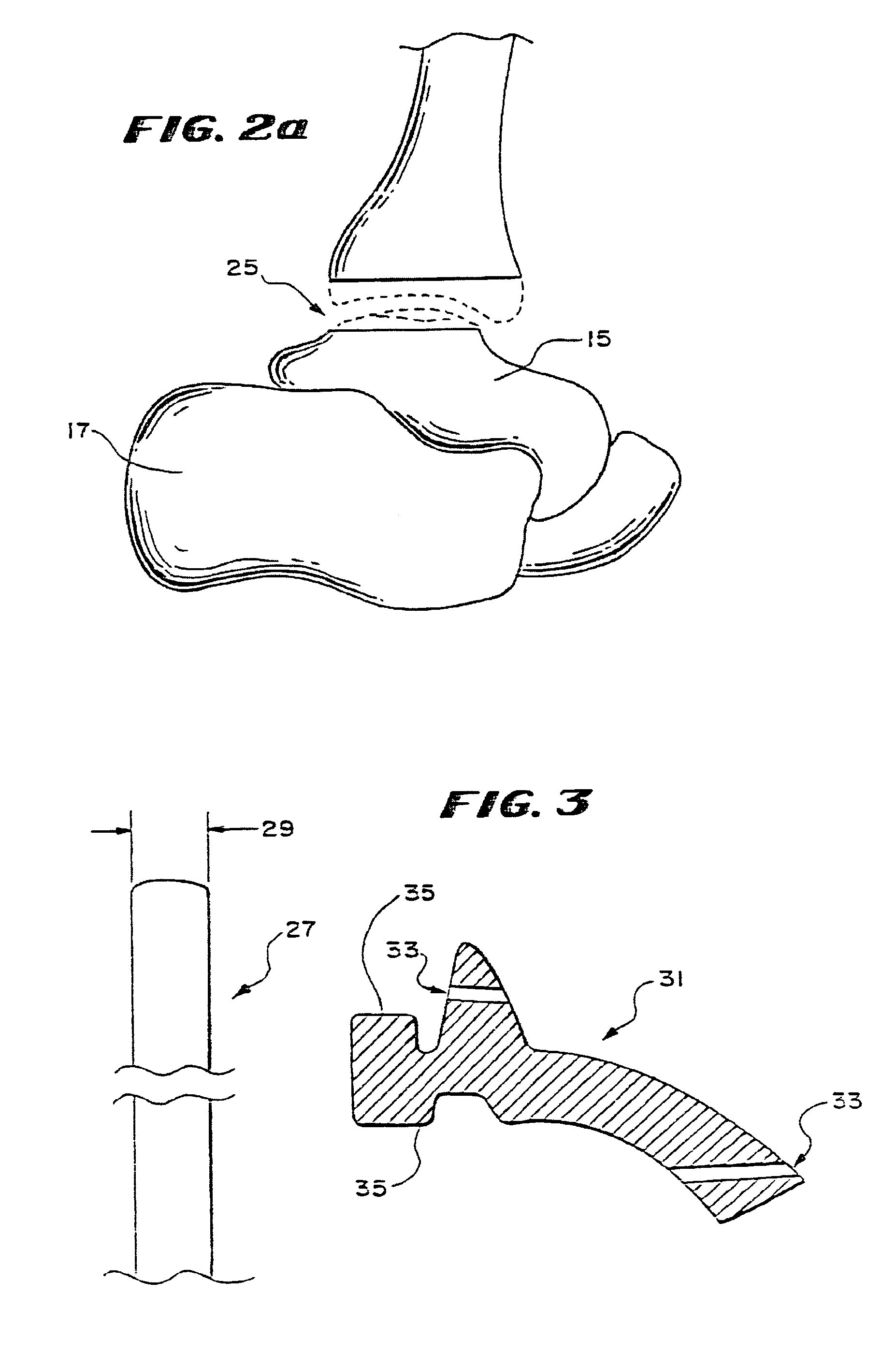
[0037]In performing a total ankle replacement procedure, it is desirable to cut away bone on the inferior end of the tibia 16 and / or the superior end of the talus 15, to thereby form a planar surface or surfaces 25, as FIG. 2 and FIG. 2a shows (in FIG. 2a, the tibia 16 and talus 15 have been resected with the removed portions shown in phantom lines, leaving two planar surfaces 25).

[0038]A planar surface increases the amount of bone available for the fixation of a selected prosthetic base. ...


PUM


Abstract

An ankle implant for use in ankle arthroplasty in total ankle replacement is provided. The implant includes an upper prosthesis anchored to the tibia and a lower prosthesis anchored to the talus. The lower prosthesis is operable associated with the upper prosthesis. The implant also includes a stem which is rigidly removably connected to the second member. The stem includes a portion for attachment to the calcaneous. The stem is be adapted to be in a first position in the calcaneous when the stem is in a first relative position with respect to the lower prosthesis, and to provide for a second position in the calcaneous when the stem is in a second relative position with respect to the lower prosthesis.

Description

RELATED APPLICATIONS[0001]This application is a continuation of U.S. patent application Ser. No. 11 / 648,042, filed Dec. 29, 2006 (now U.S. Pat. No. 8,034,114), which is a division of U.S. patent application Ser. No. 11 / 038,803, filed Jan. 19, 2005, now U.S. Pat. No. 7,314,488 which is a division of U.S. patent application Ser. No. 10 / 699,999, filed Nov. 3, 2003 (now U.S. Pat. No. 6,875,236), which is a division of U.S. patent application Ser. No. 09 / 935,479, filed Aug. 23, 2001 (now U.S. Pat. No. 6,673,116, which is a continuation-in-part of U.S. patent application Ser. No. 09 / 694,100, filed Oct. 20, 2000 (now U.S. Pat. No. 6,663,669), which claims the benefit of U.S. Provisional Patent Application Ser. No. 60 / 160,892, filed Oct. 22, 1999, all of which are incorporated herein by reference in their entireties.FIELD OF THE INVENTION[0002]The invention relates to ankle replacement prostheses, systems, and associated surgical procedures.BACKGROUND OF THE INVENTION[0003]Until the early t...

Claims


Application Information

Patent Timeline
Patent Type & Authority Patents(United States)
IPC IPC(8): A61F2/42
CPCA61B17/72A61F2/4202A61B17/1717A61B17/7258A61F2002/30331A61F2002/30332A61F2002/30604A61F2002/4205A61F2002/4207A61B2017/1775A61B17/1775A61F2/4606A61F2002/30607A61F2002/4217
Inventor REILEY, MARK A.
Owner INBONE TECH
Learn More