Motion path search device and method of searching for motion path
a technology of motion path and search device, which is applied in the direction of electric programme control, instruments, program control, etc., can solve the problem of difficulty in determining a motion path with higher optimality, and achieve the effect of efficient expansion of an accessible spa
- Summary
- Abstract
- Description
- Claims
- Application Information
AI Technical Summary
Benefits of technology
Problems solved by technology
Method used
Image
Examples
embodiment 1
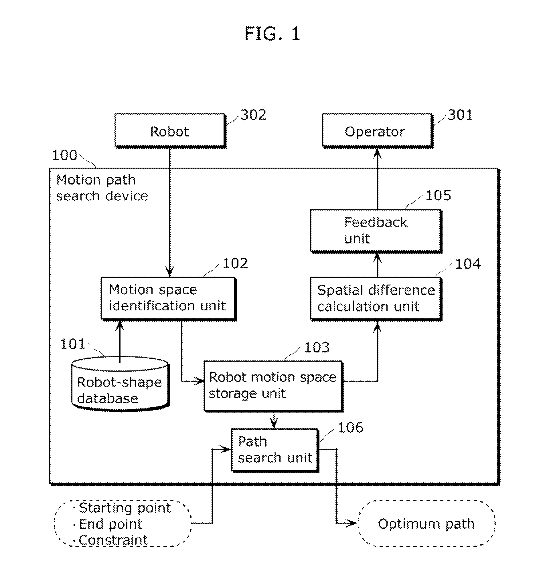
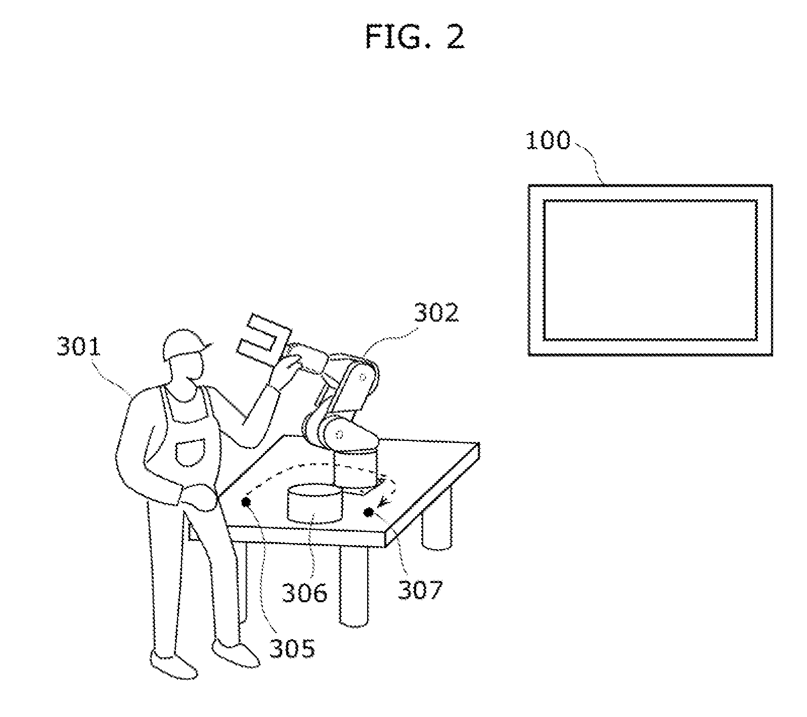
[0071]FIG. 1 is a block diagram showing a basic functional configuration of a motion path search device 100 in Embodiment 1. As shown in FIG. 1, the motion path search device 100 includes a robot-shape database 101, a motion space identification unit 102, a robot motion space storage unit 103, a spatial difference calculation unit 104, a feedback unit 105, and a path search unit 106.
[0072]The robot-shape database 101 stores robot-shape data indicating the shape of a robot 302 which performs automated operation.
[0073]The motion space identification unit 102 corresponds to a first space identification unit. The motion space identification unit 102 identifies, as a first space (hereinafter referred to as a “robot motion space”), a three-dimensional space swept through by a movable part in each direct teaching operation.
[0074]Specifically, the motion space identification unit 102 identifies a three-dimensional space occupied by the robot 302 at points of time in direct teaching, based o...
embodiment 2
[0142]Embodiment 2 of the present disclosure shall be described below with reference to the drawings. The description of the part in common with Embodiment 1 will not be repeated herein.
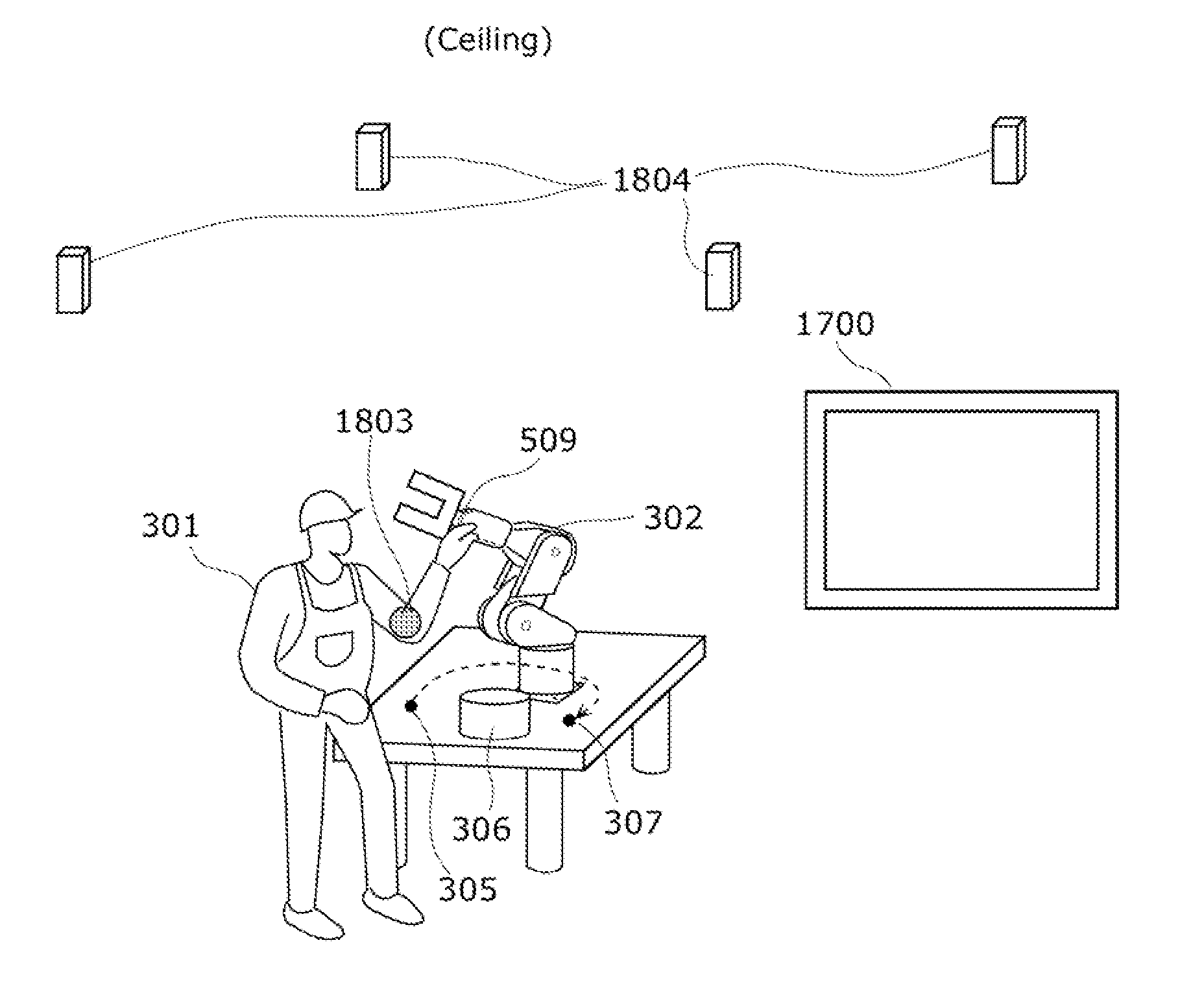
[0143]A motion path search device 1700 in Embodiment 2 is different from the motion path search device 100 in Embodiment 1 mainly in that the motion path search device 1700 also uses a space swept through by the body of the operator 301 in direct teaching as a search space for a motion path.
[0144]FIG. 17 is a block diagram showing a basic functional configuration of the motion path search device 1700 in Embodiment 2. The components in common with those in FIG. 1 are denoted with the same reference signs in FIG. 17 and the description thereof is not repeated herein.
[0145]As shown in FIG. 17, the motion path search device 1700 includes a robot-shape database 101, a motion space identification unit, 102, and a robot motion space storage unit 103 as is the case with the motion path search device 100 in E...
embodiment 3
[0202]Embodiment 3 of the present disclosure shall be described below with reference to the drawings. The description of the part in common with Embodiment 2 will be omitted herein as appropriate.
[0203]A motion path search device according to Embodiment 3 is different from the motion path search device in Embodiment 2 in that the information to be provided to the operator 301 varies depending on a result of comparison between a first differential space and a second differential space. The functional configuration of the motion path search device in Embodiment 3 is not illustrated in the drawings because it is in common with that in Embodiment 2.
[0204]In Embodiment 3, a feedback unit 1709 provides one of information regarding a first differential space and information regarding a second differential space depending on a result of comparison between the first differential space and the second differential space. Specifically, the feedback unit 1709 provides information regarding the f...
PUM
 Abstract
Description
Claims
Application Information
 - R&D
- Intellectual Property
- Life Sciences
- Materials
- Tech Scout
- Unparalleled Data Quality
- Higher Quality Content
- 60% Fewer Hallucinations
Browse by: Latest US Patents, China's latest patents, Technical Efficacy Thesaurus, Application Domain, Technology Topic, Popular Technical Reports.
© 2025 PatSnap. All rights reserved.Legal|Privacy policy|Modern Slavery Act Transparency Statement|Sitemap|About US| Contact US: help@patsnap.com


