
Method and apparatus for stimulating pelvic floor muscles

a pelvic floor and muscle technology, applied in the field of pelvic floor muscle stimulation, can solve the problems of difficult to produce effective voluntary contractions, poor patient comfort level, and less appeal to many patients and clinicians, and achieve good recruitment of pelvic floor muscles.

Active Publication Date: 2013-07-23
UNIV COLLEGE DUBLIN NAT UNIV OF IRELAND DUBLIN +1
View PDF8 Cites 21 Cited by
  • Summary
  • Abstract
  • Description
  • Claims
  • Application Information

AI Technical Summary

Benefits of technology

This approach provides significant pelvic floor muscle recruitment, improving incontinence management and patient comfort, with acute effects demonstrated through ultrasound imaging and clinical testing, offering a more effective and tolerable treatment for stress urinary incontinence and potentially other incontinence conditions.

Problems solved by technology

Stress urinary incontinence (SUI) is a major medical problem that affects up to one third of middle aged women and has a significant impact on quality of life.
As with any muscle, these muscles will respond well to strengthening and re-education yet patients with SUI often find it very difficult to produce the effective voluntary contractions necessary for successful rehabilitation—due a combination of difficulty in establishing conscious control and disuse atrophy.
By definition these probes are invasive and thus less appealing to many patients and clinicians.
Patient comfort levels tend to be poor and the probe can also cause local tissue trauma with associated post treatment bleeding and tenderness.
Whilst these invasive electrodes induce some pelvic floor contraction it is typically of limited strength; thus reducing its likely efficacy.
Current density around the area of the invasive electrode is high leading to an uncomfortable sensation for the patient, this is exacerbated by the tendency of the electrodes to fall away from the tissue.
Further to this, the invasive electrodes can also cause minor tissue damage leading to further discomfort.
This greatly limits the tolerance of NMES as a therapeutic approach for SUI and rehabilitation gains are often limited by poor compliance as a result.
However, the strength of contractions produced by these external electrode systems were generally poor and unpredictable and more recent approaches to using NMES in SUI treatment have employed an invasive approach.

Method used


Image

  • Method and apparatus for stimulating pelvic floor muscles
  • Method and apparatus for stimulating pelvic floor muscles
  • Method and apparatus for stimulating pelvic floor muscles

Examples


Embodiment Construction

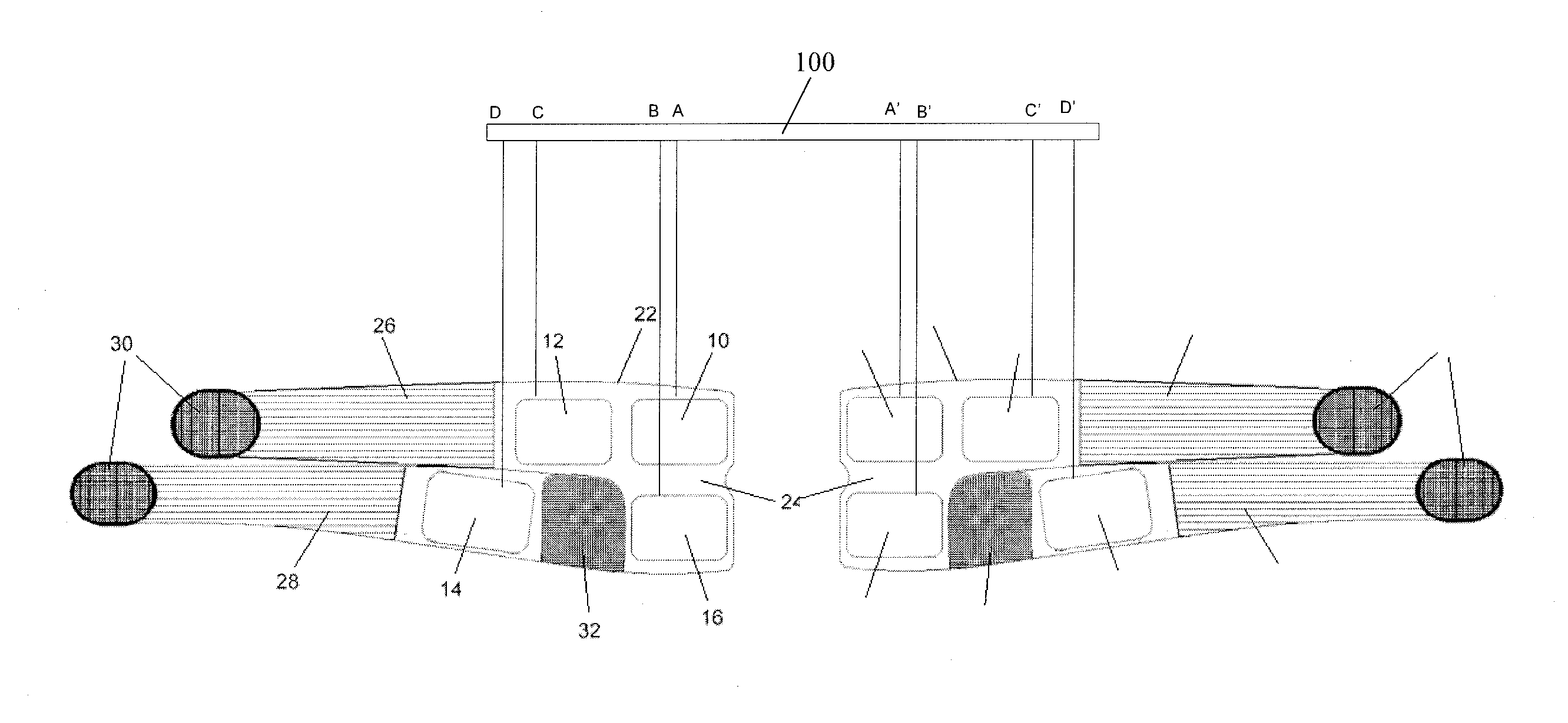
[0024]Referring to FIG. 1, in the embodiment a method of treating stress urinary incontinence in a patient comprises applying a respective set of large-area electrodes 10 to 16 externally to each side of the patient's body 18 in the region of the pelvis. The two sets of electrodes are disposed on the patient's skin at least approximately symmetrically relative to the patient's midline 20. The electrodes comprise, on each side of the body 18, a first electrode 10 on the posterior pelvic, close to the mid-line cleft, centred near or below the point of maximum convexity, a second electrode 12 on the hip approximately horizontally in line with the electrode 10, a third electrode 14 on the upper front thigh, and a fourth electrode 16 on the upper back thigh. As used herein, expressions of orientation such as “vertical” and “horizontal” refer to the patient when standing. Contact wires (not shown) are connected individually to the electrodes which allow a muscular stimulation current to b...


PUM


Abstract

A method of and apparatus for stimulating pelvic floor muscles in a patient comprises applying at least one electrode externally to each side of the patient's body in the region of the pelvis, and energising the electrodes to apply a muscular stimulation current which flows laterally across the patient through the patient's pelvic floor. Preferably a plurality of electrodes are applied symmetrically on each side of the body. The electrodes may be incorporated in a garment.

Description

[0001]This is a National Phase Application filed under 35 U.S.C. 371 as a national stage of PCT / IB2010 / 000018, filed on 8 Jan. 2010, an application claiming the benefit from Irish Application No. S2009 / 0076, filed on 26 Jan. 2009, the entire content of each of which is hereby incorporated by reference in its entirety.[0002]This invention relates to a method and apparatus for stimulating pelvic floor muscles in a patient, especially but not limited to stimulating such muscles to treat stress urinary incontinence.BACKGROUND[0003]Stress urinary incontinence (SUI) is a major medical problem that affects up to one third of middle aged women and has a significant impact on quality of life. A major contributing factor to the development of SUI is weakness and dysfunctional reflex activation of the muscles of the pelvic floor during times of increased bladder pressure. As with any muscle, these muscles will respond well to strengthening and re-education yet patients with SUI often find it v...

Claims


Application Information

Patent Timeline
Patent Type & Authority Patents(United States)
IPC IPC(8): A61N1/04
CPCA61N1/0452A61N1/0476A61N1/36007A61N1/321A61N1/0484
Inventor CROWE, LOUISCAULFIELD, BRIANMAHER, RUTHMINOGUE, CONOR
Owner UNIV COLLEGE DUBLIN NAT UNIV OF IRELAND DUBLIN
Learn More