Load restraint assembly

a technology for restraints and load plates, applied in the direction of reel unit transportation, transportation items, vehicle carriers, etc., can solve the problems of unsafe transport of coils, metal coils are typically very heavy, and are difficult to handl

Inactive Publication Date: 2013-07-23
FERRARI INVESTMENTS
View PDF10 Cites 12 Cited by
  • Summary
  • Abstract
  • Description
  • Claims
  • Application Information

AI Technical Summary

Benefits of technology

[0009]The combination of the members (which may be formed as locking members) and the openings is a convenient and effective means of securely locating a chock on a tray. More particularly, the arrangement takes advantage of the inherent strength and rigidity of the tray structure to locate, and preferably securely retain, the chock in a selected position. The use of a line of spaced-apart openings provides an opportunity for considerable flexibility to position the chock on the tray. Moreover, the arrangement makes it possible to use chocks that are relatively lightweight compared to blocks of timber. This is an important issue from the health and safety viewpoint. Such chocks are considerably easier to lift and locate on a tray and to store when not being used. Moreover, such chocks make it possible to reduce the time currently required to locate and / or restrain a load on a tray.
[0018]Typically, the chock comprises cut-outs that form a hand grip for ease of lifting the chock. The hand-grips also minimise the weight of the chocks.

Problems solved by technology

Metal coils are typically very heavy, ranging from two to eighteen tonnes but most commonly between four and twelve tonnes, and difficult to handle.
This is an inherently unstable orientation for metal coils, and given the weight of coils, is a potentially very unsafe way of transporting coils.
However, the use of timber chocks and coil racks is unsatisfactory because of the heavy weight of the timber and the racks and the manhandling required to locate the chocks properly in the first place and then removing and stowing the chocks after a truck reaches a destination and offloads the coils.
The Robo-rack device renders the tray unusable on a return journey due to its weight and the space it occupies on the tray.
This is an important issue from the health and safety viewpoint.

Method used


Image

  • Load restraint assembly
  • Load restraint assembly
  • Load restraint assembly

Examples


Embodiment Construction

[0057]The following description is in the context of a tray of a truck for carrying a load in the form of coils of steel strip, with the coils being positioned on their sides, i.e. on the outer circumference of the coils, on the tray, so that the rotary centrelines of the coils are perpendicular to the length direction of the tray.

[0058]The following description is also in the context of a tray of a truck for also carrying long products, such as bundles of steel reinforcing and plate steel and steel channel sections and steel pipes on the tray.

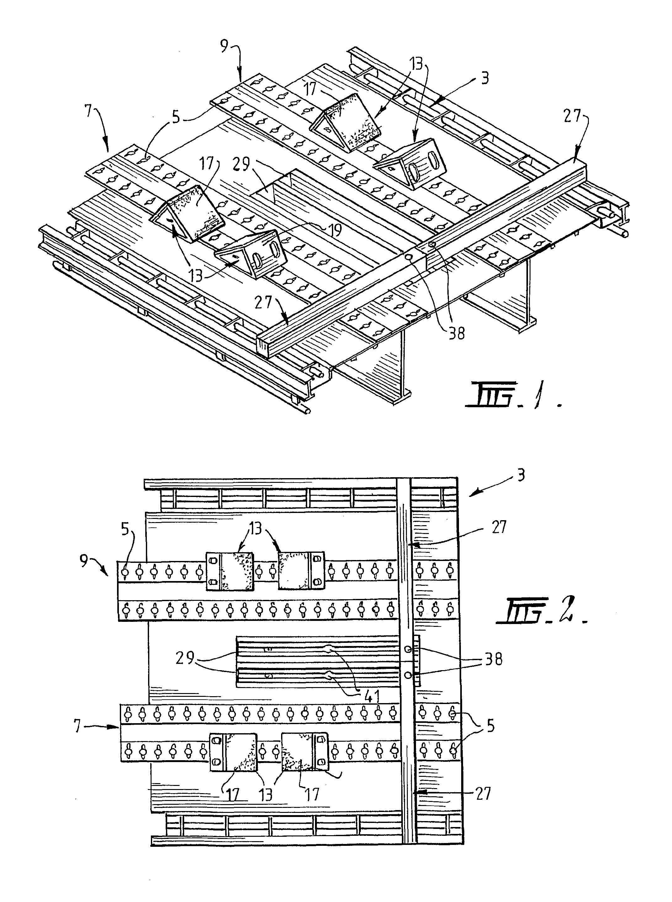
[0059]The tray 3 shown in FIG. 1 has four parallel lines of openings in the form of keyholes 5 cut in the tray. The keyholes 5 have a constant spacing in each line. Typically, the centre-centre spacing of the keyholes is 100 cm. The selection of the spacing is purely a function of the load to be carried on the tray. The spacing does not have to be constant.

[0060]The lines of the keyholes 5 are arranged in two pairs of lines. The lines in each ...


PUM


Abstract

An assembly for locating and / or restraining a load carried on a tray of a truck or other vehicle. The assembly includes at least one line of openings such as keyholes in the tray at spaced intervals along at least a part of the length of a tray. The assembly also includes at least one chock for locating and / or restraining a load against forward or rearward movement on the tray, with the chock having a locking member that is adapted to be received in the openings so that the chock can be supported and retained in a selected position on the tray. The assembly also includes at least one bearer for locating and supporting a load, such as long products, on the tray.

Description

BACKGROUND OF THE INVENTION[0001]The present invention relates to an assembly for locating and / or restraining loads carried on trays of trucks or other vehicles.[0002]The present invention relates particularly, although by no means exclusively, to an assembly for locating and / or restraining loads in the form of coils of metal strip, such as steel strip.[0003]Metal coils are typically very heavy, ranging from two to eighteen tonnes but most commonly between four and twelve tonnes, and difficult to handle. An important consideration for transporting metal coils is to locate and then restrain the coils securely on a truck tray. Metal coils are usually transported on their sides, i.e. on the outer circumference of the coils, to facilitate handling the coils via forklifts or other lifting devices onto and off truck trays. This is an inherently unstable orientation for metal coils, and given the weight of coils, is a potentially very unsafe way of transporting coils. Hence, it is necessar...

Claims


Application Information

Patent Timeline
Patent Type & Authority Patents(United States)
IPC IPC(8): B60P7/08
CPCB60P7/12B60P3/035
Inventor FERRARI, PETER WARREN
Owner FERRARI INVESTMENTS
Why Eureka
Try Eureka